High-efficiency coupling dust remover applicable to desulfurization dust-removing absorption tower and dust removing method thereof

A technology for desulfurization and dedusting and dedusting, which is applied in the direction of chemical instruments and methods, separation methods, combined devices, etc., can solve the problems of large flushing water volume of the plate and the decline of dust removal efficiency, and achieve the purpose of promoting condensation to become larger, increasing accumulation speed, and increasing The effect of removal efficiency

Active Publication Date: 2016-07-27
SHANGHAI LONGKING ENVIRONMENTAL PROTECTION
View PDF5 Cites 2 Cited by
  • Summary
  • Abstract
  • Description
  • Claims
  • Application Information

AI Technical Summary

Problems solved by technology

However, the existing wet electrostatic precipitator still has disadvantages such as the decrease of dust removal efficiency after the attachment of large particles and the large amount of washing water for the plate, and there is still room for further improvement and improvement

Method used


Image

  • High-efficiency coupling dust remover applicable to desulfurization dust-removing absorption tower and dust removing method thereof
  • High-efficiency coupling dust remover applicable to desulfurization dust-removing absorption tower and dust removing method thereof
  • High-efficiency coupling dust remover applicable to desulfurization dust-removing absorption tower and dust removing method thereof

Examples


Embodiment Construction

[0046] In order to more clearly illustrate the embodiments of the present invention or the technical solutions in the prior art, the specific implementation manners of the present invention will be described below with reference to the accompanying drawings. Obviously, the accompanying drawings in the following description are only some embodiments of the present invention, and those skilled in the art can obtain other accompanying drawings based on these drawings and obtain other implementations.

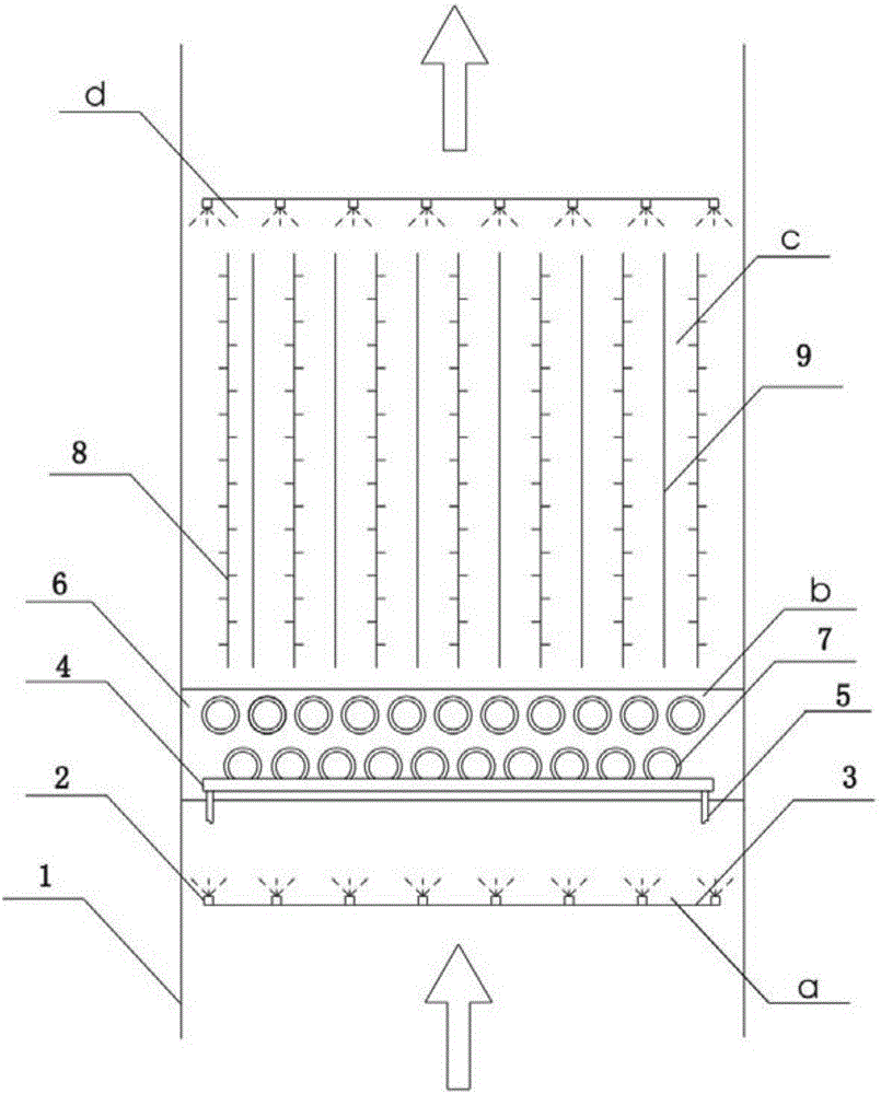
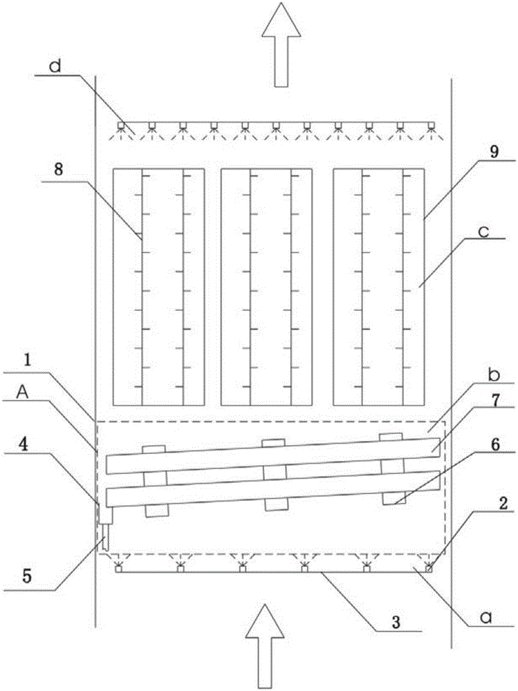
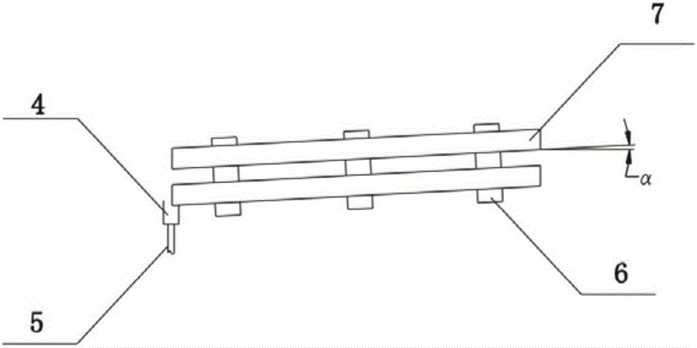
[0047] In Embodiment 1 of the present invention, see figure 1 , 2 , the high-efficiency coupling dust collector is set inside the absorption tower 1, and the flue gas to be treated flows in from the entrance of the absorption tower 1 and then passes through the impact dust removal area b, the electric field dust removal area c, and the flushing spray layer d of the high-efficiency coupling dust collector, and finally from The outlet of the absorption tower 1 flows out in a vertic...


PUM


Abstract

The invention discloses a high-efficiency coupling dust remover applicable to a desulfurization dust-removing absorption tower and a dust removing method thereof. The high-efficiency coupling dust remover comprises an impact dust-removing area, an electric-field dust-removing area and a washing and spraying layer, wherein the impact dust-removing area comprises two or more rows of round pipe layers which are arranged in parallel from top to bottom, and each two adjacent upper and lower rows of round pipe layers are arranged in a staggering manner; the electric-field dust-removing area comprises an anode plate for collecting dust and a cathode line for discharging; the washing and spraying layer is arranged above the electric-field dust-removing area; flue gas flows through the impact dust-removing area, the electric-field dust-removing area and the washing and spraying layer in sequence. The dust removing method comprises the following steps: carrying out impact treatment on flue gas to be treated entering from a flue-gas inlet; carrying out electric-field force adsorption treatment on the flue gas after impact treatment; and carrying out intermittent or continuous spraying cleaning on the anode plate and the cathode line. The high-efficiency coupling dust remover disclosed by the invention has the advantages that high-efficiency and stable operation of the dust remover can be effectively guaranteed, the efficiency of removing fine particles in the flue gas can be improved and thus the requirement on ultraclean emission of particles is met.

Description

technical field [0001] The invention belongs to the technical field of air pollution prevention and control, in particular to a high-efficiency coupling dust collector and a dust removal method suitable for a desulfurization dust removal absorption tower. Background technique [0002] Following the release of the "Notice on Issues Concerning the Implementation of Ultra-Low Emission Power Price Support Policies for Coal-fired Power Plants" in early December 2015, the Ministry of Environmental Protection, the National Development and Reform Commission, and the Energy Bureau issued the "Comprehensive Implementation of Ultra-Low Emission and Energy-Saving Transformation Work Plans for Coal-fired Power Plants" in the same month. ", to clarify the timetable for ultra-low emissions. The comprehensive implementation of ultra-low emission and energy-saving transformation of coal-fired power plants is an important measure to promote the clean utilization of coal, improve the quality o...

Claims


Application Information

Patent Timeline
Patent Type & Authority Applications(China)
IPC IPC(8): B01D50/00
CPCB01D2258/0283B01D50/40
Inventor 任世中陈天光何永胜方巧
Owner SHANGHAI LONGKING ENVIRONMENTAL PROTECTION
Why Eureka
Try Eureka