Assembled method of electric connector and structure thereof

An assembly method and technology for electrical connectors, applied in the directions of assembly/disassembly of contacts, connection/disconnection of connecting devices, fixation/insulation of contact members, etc.

Inactive Publication Date: 2012-01-04
DEYI PRECISION ELECTRONIC IND CO LTD PANYU
View PDF0 Cites 0 Cited by
  • Summary
  • Abstract
  • Description
  • Claims
  • Application Information

AI Technical Summary

Problems solved by technology

[0002]At present, the assembly method of electrical connectors commonly used in the industry is to form two sets of different conductive terminals, and then rive the two sets of different conductive terminals into the insulation The main body interferes with the insulating body, and the two conductive terminal groups are installed and fixed together in the same accommodation space of the same tongue plate of the insulating body, but the two conductive terminal groups are installed and fixed together in the same receiving space of the insulating body. When the insulating body is placed in the insulating body, due to the limited storage space, when the lowest point of the upper conductive terminal group is lower than the highest point of the lower conductive terminal group, the two conductive terminal groups are prone to damage during assembly. Interference, the phenomenon that the conductive terminal group is not easy to assemble

Method used


Image

  • Assembled method of electric connector and structure thereof
  • Assembled method of electric connector and structure thereof
  • Assembled method of electric connector and structure thereof

Examples


Embodiment Construction

[0020] The assembly method and structure of the electrical connector of the present invention will be further described below with reference to the drawings and specific embodiments.

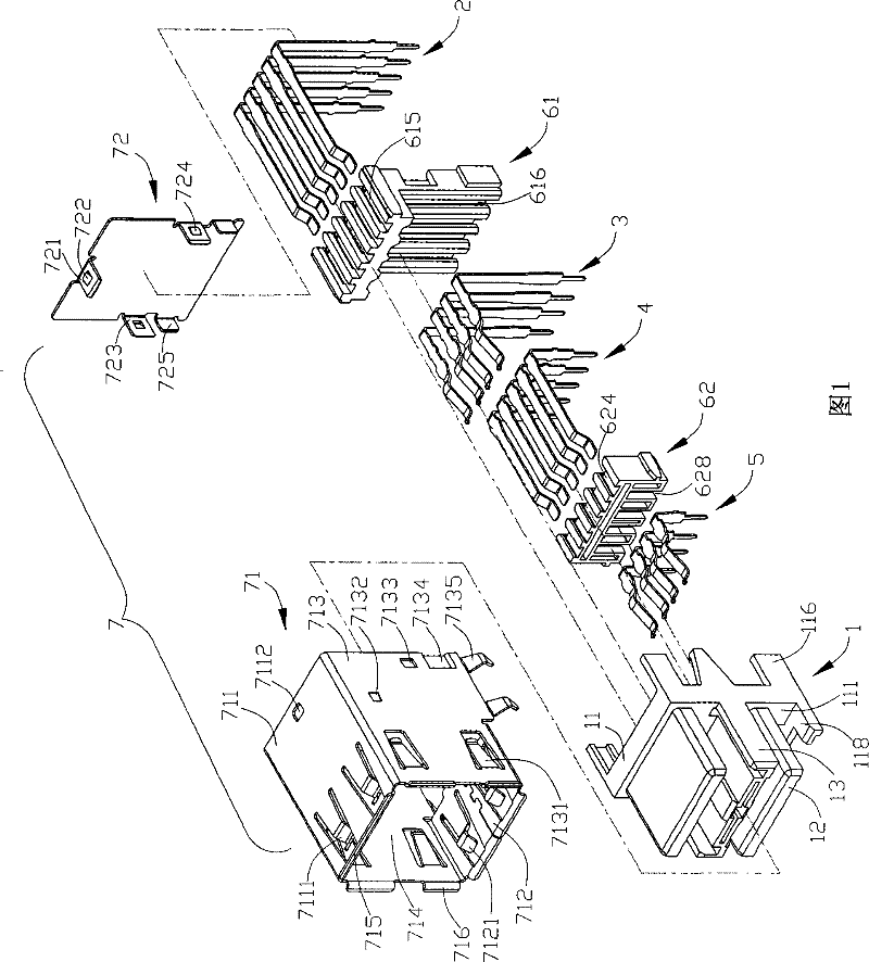
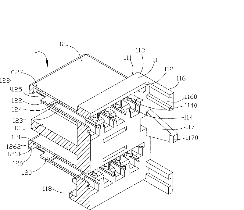
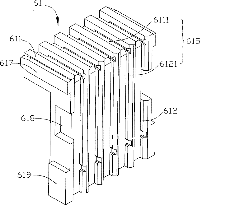
[0021] Please refer to Figure 1 to Figure 11 , the electrical connector in the present invention includes a first body 1, a first conductive terminal group 2, a second conductive terminal group 3, a third conductive terminal group 4, a fourth conductive terminal group 5, two second The main body and a shielding case 7 . Wherein, the second conductive terminal group 3 and the first conductive terminal group 2 are conductive terminals for transmitting signals at two different speeds, and the third conductive terminal group 4 and the first conductive terminal group 2 are the same a kind of conductive terminal, the fourth conductive terminal group 5 and the second conductive terminal group 3 are the same kind of conductive terminals, and the two second bodies are respectively a first rear plug 61 ...


PUM


Abstract

An assembling method of the electric connector of the invention includes the following steps: (1) providing a first body arranged with a holding space and at least a second body; (2) providing a first conduction terminal set and a second conduction terminal set corresponding to the second body; (3) assembling the first conduction terminal set and the second conduction terminal set on the second body, to cause a first wall spring of the first conduction terminal set adjacent with a second wall spring of the second conduction terminal set on the same plane; (4) assembling the second body in the first body, to cause the first wall spring and the second wall spring to enter the holding space. The invention avoids the interference of the first and the second conduction terminal sets because of the inadequate holding space of the first body, furthermore avoids the difficult installment of the first and the second conduction terminal sets, moreover, the first and the second conduction terminal sets are assembled into the same holding space, which realizes the dense arrangement of the conduction terminal.

Description

【Technical field】 [0001] The invention relates to an assembly method of an electrical connector. 【Background technique】 [0002] The assembly method of electrical connectors commonly used in the industry is to form two sets of different conductive terminals, and then rivet the two sets of different conductive terminals into the insulating body to interfere with the insulating body, and the two conductive terminals The groups are installed and fixed together in the same accommodation space of the same tongue plate of the insulating body, but when the two conductive terminal groups are installed and fixed together in the insulating body, due to the limited accommodation space, when the upper When the lowest point of the conductive terminal group is lower than the highest point of the lower conductive terminal group, the two conductive terminal groups are likely to interfere during the assembly process, and the conductive terminal group is difficult to assemble. [0003] Ther...

Claims


Application Information

Patent Timeline
Patent Type & Authority Patents(China)
IPC IPC(8): H01R13/42H01R43/20H01R43/26
Inventor 胡德芳
Owner DEYI PRECISION ELECTRONIC IND CO LTD PANYU
Why Eureka
Try Eureka