
Fire arm collimating tool

A technology of sights and light weapons, applied in the field of n-type front sight guards, can solve the problems of low accuracy, difficult repair, increase in volume and weight, etc., and achieve the effect of improving aiming accuracy and saving aiming time.

Inactive Publication Date: 2008-11-19
佘运强
View PDF0 Cites 3 Cited by
  • Summary
  • Abstract
  • Description
  • Claims
  • Application Information

AI Technical Summary

Problems solved by technology

[0002] Now, the disadvantages of the traditional front sight and notched mechanical sight on various firearms such as pistols and various submachine guns with a history of hundreds of years: when aiming at the traditional front sight notch, there is a slight deviation in the center. Bullet deviation, it is just the flat point on the top of the front sight post and the leveling of the notch concave surface, it is difficult to level up when aiming, the vignetting is large, and it is not easy to center, which not only affects the shooting accuracy, but also wastes aiming time
Therefore, we can only roughly estimate the aiming, and the accuracy of aiming is reduced. The disadvantage of the newly used Type 95 submachine gun is that it blocks the line of sight. Due to the distance between the line of sight and the viewing hole, it is easy to cause errors, and the aiming is laborious and the accuracy is not high.
When aiming, the exposed target is too large, and the optical sights currently used also have certain disadvantages: the optical sights cannot be fully integrated with the barrels of various submachine guns, and it can only be an accessory of the gun. Volume and weight, carrying and maintenance, time-consuming and labor-intensive, and high cost, bulky, large, afraid of collision, afraid of falling, easy to break, difficult to repair, afraid of waterproof when armed swimming, difficult to protect, not suitable for use with pistols
So it can only be used under certain circumstances

Method used


Image

  • Fire arm collimating tool

Examples


Embodiment Construction

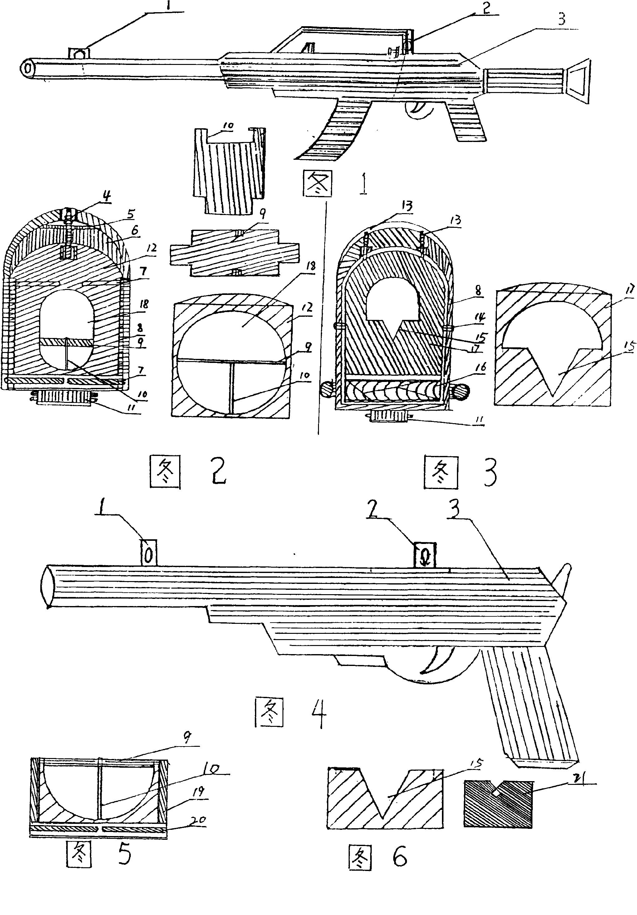
[0015] As shown in Figures 1-6, Figures 1-3 show the configuration diagram of the charging aiming device. A screw 7, the top screw 4 is inserted from the draw-in groove slide plate 5 at the top of the nail hole to connect the front sight plate 12, and adjusted in the n-type retainer 8, which is the front sight device and fixed tightly. And be connected with gun body 3 connecting shaft 11. Notch position: set the V-shaped plate 17 of the iron sheet round cover with the inner groove of the n-shaped retainer 8. Tighten the two positioning nails and telescopic spring 13 at the top, put the scale roller 16 into the lower end of the n-type retainer, adjust and fix the V-shaped plate 17 and n retainer 8 with rivets 14, turn the scale roller to move the gap height up and down, and then the gap device 15 Combining with the charging notch 2, the installation is complete. Wherein Fig. 4-Fig. 6 shows pistol sight device configuration diagram, the T-type front sight plate 9,10 in Fig. 5 ...


PUM


Abstract

The invention discloses a novel method of aiming means of a gunsight of a light weapon, which is structurally characterized in that a T-shaped bead sight plate is arranged on the position of bead sight of a handgun or a submachine gun, and a V-shaped or X-shaped gap plate is arranged on the position of gap with that the bead sight and the gap can be moved and adjusted up and down or left and right flexibly and eliminate part of false light effectively. The line of sight passes through the top of the V-shaped gap plate and is aligned with the T-shaped bead sight plate in the middle when aiming so that one can fire. The principle of aiming is the same with that of the traditional technique. The gunsight of the light weapon approximates to a sighting telescope, and is made of metal, hard to be destroyed, cheaply produced, easy to carry, high in aiming accuracy, low in error rate, simple and convenient, thereby improving the striking force effectively without any environmental restriction. The aiming accuracy fills the gap of mechanical aiming throughout the world.

Description

Technical field [0001] The technology of the present invention relates to the n-type front sight retainer used on various light weapon firearms, and the iron plate round hole row virtual mask type T-type front sight, V-type or X-shaped notch light weapon firearm sight are installed inside. Background technique [0002] Now, the disadvantages of the traditional front sight and notched mechanical sight on various firearms such as pistols and various submachine guns with a history of hundreds of years: when aiming at the traditional front sight notch, there is a slight deviation in the center. The bullet deviation is just the leveling of the flat point on the top of the sight post and the concave surface of the notch. It is difficult to level up when aiming. The vignetting is large and it is not easy to center, which not only affects the shooting accuracy, but also wastes aiming time. Therefore, aiming can only be roughly estimated, and the accuracy of aiming is reduced. When a...

Claims


Application Information

Patent Timeline
Patent Type & Authority Applications(China)
IPC IPC(8): F41G1/01F41G1/10
Inventor 佘运强
Owner 佘运强
Learn More