Belt drive

A transmission, main vibration technology, used in transmissions, valve drives, valve devices, etc.

Inactive Publication Date: 2008-11-19
SCHAEFFLER TECH AG & CO KG
View PDF1 Cites 10 Cited by
  • Summary
  • Abstract
  • Description
  • Claims
  • Application Information

AI Technical Summary

Problems solved by technology

While this makes the drive apparently stable, there are always residual disturbing vibrations

Method used


Image

  • Belt drive
  • Belt drive
  • Belt drive

Examples


Embodiment Construction

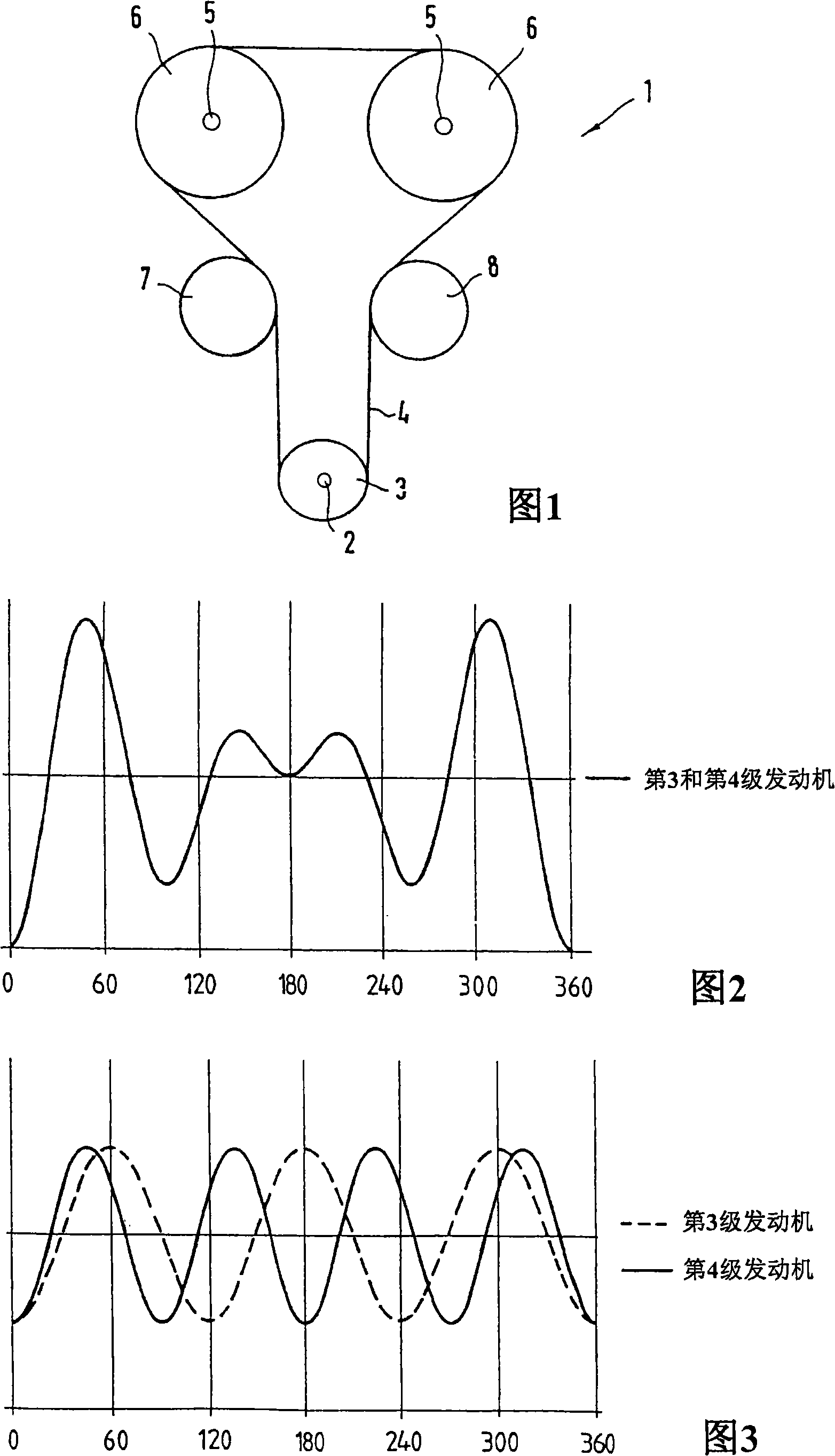
[0019] FIG. 1 shows a schematic diagram of a conventional winding transmission 1 , such as is found, for example, in internal combustion engines of motor vehicles. Located on the crankshaft 2 is a first pulley 3 which is wound by a traction element 4 (belt or chain). On each of the two camshafts 5 is seated a wheel 6 which is likewise wound by the traction element 4 . Furthermore, there is a tensioning device 7 which can be a tensioning pulley if the traction means 4 is a belt. If the traction means 4 is a chain, the tensioning device 7 is designed as a tensioning disk. On the opposite return section of the traction element 4 there is a guide 8 by which the traction element 4 is guided. On a belt, the guide 8 is a deflection wheel, in the case of a chain it is a guide rail. The basic structure of the winding drive is already known and does not need to be described in detail.

[0020] During operation, disturbing vibrations are transmitted to the winding drive 1 or the trac...


PUM


Abstract

The invention relates to a belt drive (1) comprising belt drive means (4) such as a belt or a chain and a plurality of wheels (1, 6, 7, 8), sitting on shafts and integrated into the drive, around which the belt drive is wound, parasitic oscillations being introduced into the belt drive (1) by means of at least one shaft. For the purpose of generating a counter-oscillation, at least one wheel (3) has a noncircular shape. Said noncircular wheel (3) is configured, in terms of its shape, in such a manner that it is adapted to generate a counter-oscillation which compensates at least two different main oscillation orders of the parasitic oscillation.

Description

technical field [0001] The invention relates to a winding transmission, comprising a winding element such as a belt or a chain and a plurality of wheels integrated with the transmission, wound by the winding element and positioned on a shaft, wherein disturbing vibrations are introduced into the winding transmission through at least one shaft, And wherein at least one wheel has a non-circular shape in order to generate counter-vibrations. Background technique [0002] Wound transmissions of this type are generally used primarily in internal combustion engines in the automotive sector. The transmission is generally driven by a wheel that cooperates with the crankshaft. Through a traction member such as a belt, the corresponding transmission wheel is also matched with it, such as one or more camshafts, and other auxiliary units such as water pumps, air-conditioning compressors, etc. are connected to the transmission through the corresponding wheels and passed through the tran...

Claims


Application Information

Patent Timeline
Patent Type & Authority Applications(China)
IPC IPC(8): F16H55/08F16H35/02F01L1/02
CPCF16H7/023F16H55/14F16H55/084F01L1/02F16H2035/003F01L1/024F16H55/08F16H35/02
Inventor 罗曼·克恩雷纳·普夫卢格
Owner SCHAEFFLER TECH AG & CO KG
Why Eureka
Try Eureka