Hermetic compressor

A hermetic compressor and reed technology, applied in the field of compressors, can solve problems such as reduced efficiency of hermetic compressors

Active Publication Date: 2008-11-26
PANASONIC APPLIANCES REFRIGERATION DEVICES SINGAPORE
View PDF1 Cites 3 Cited by
  • Summary
  • Abstract
  • Description
  • Claims
  • Application Information

AI Technical Summary

Problems solved by technology

As a result, the efficiency of hermetic compressors is detrimentally reduced

Method used


Image

  • Hermetic compressor
  • Hermetic compressor
  • Hermetic compressor

Examples


Embodiment Construction

[0034] Hereinafter, typical embodiments of the compressor of the present invention will be described with reference to the accompanying drawings.

[0035] first exemplary embodiment

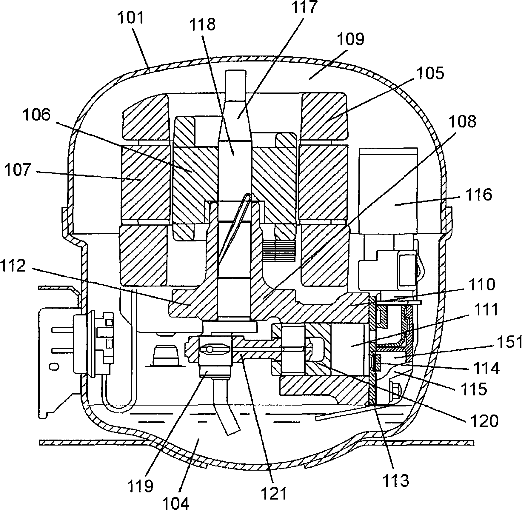
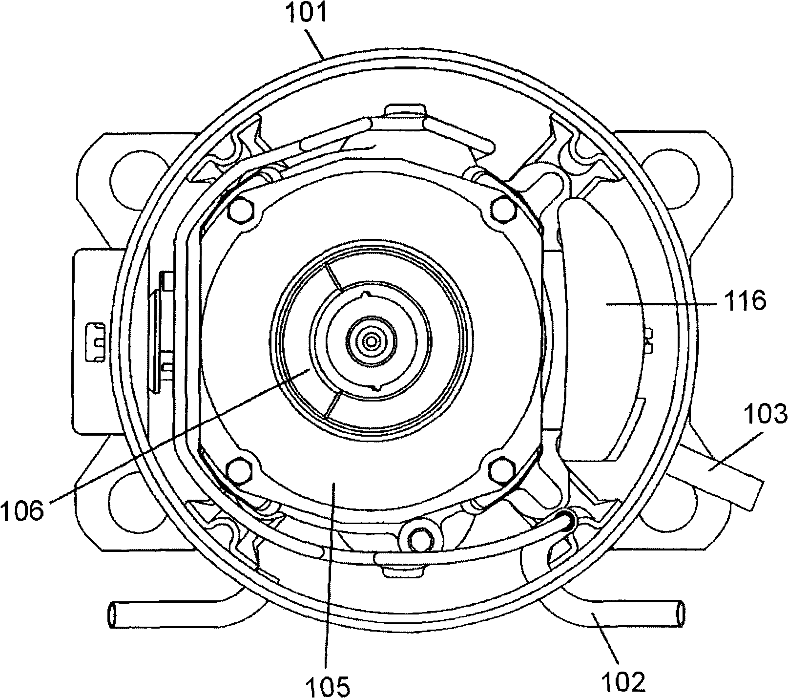
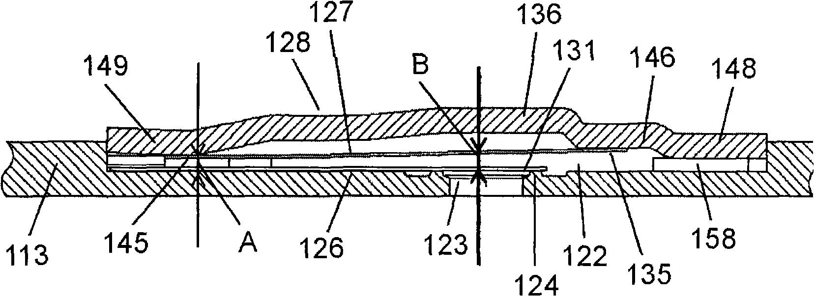
[0036] figure 1 is a sectional view of a hermetic compressor according to a typical embodiment 1 of the present invention. figure 2 is a plan view of the hermetic compressor according to exemplary embodiment 1. image 3 is a side sectional view of the discharge valve device of the hermetic compressor according to exemplary embodiment 1. Figure 4 is an exploded view of the discharge valve device of the hermetic compressor according to exemplary embodiment 1. Figure 5 is a bottom view of the stopper of the hermetic compressor according to exemplary embodiment 1. Figure 6 is a spring characteristic diagram of the hermetic compressor according to Exemplary Embodiment 1.

[0037] exist figure 1 , figure 2 , image 3 , Figure 4 , Figure 5 and Figure 6 In it, a closed housing 101 ...


PUM


Abstract

A hermetic compressor has a structure where a spring reed is separated from a discharge reed at its fixed end by a determined clearance and separated from it at an opening / closing section of the discharge reed by a clearance larger than that at the fixed end. This structure allows increase in distance between the discharge reed and a movable section of the spring reed at a position corresponding to the opening / closing section of the discharge reed. Therefore, the displacement range having a small spring constant can be extended at the beginning of opening of the discharge reed, so that the spring characteristic of a discharge valve device can be increased.

Description

technical field [0001] The present invention relates to a compressor used in refrigerator refrigerators and the like. Background technique [0002] As disclosed in, for example, Japanese Patent Laid-Open Publication No. H09-105383, some conventional hermetic compressors have a discharge valve arrangement that reduces loss during opening / closing of the discharge reed. To reduce noise during operation and improve energy efficiency. [0003] A conventional hermetic compressor will be described below with reference to the accompanying drawings. [0004] Figure 7 It is a sectional view of a conventional hermetic compressor. Figure 8 It is a side sectional view of a discharge valve device of a conventional hermetic compressor. Figure 9 It is an exploded view of the discharge valve device of a conventional hermetic compressor. Figure 10 is the spring characteristic diagram of a traditional hermetic compressor. [0005] exist Figure 7 , Figure 8 , Figure 9 and Figure...

Claims


Application Information

Patent Timeline
Patent Type & Authority Applications(China)
IPC IPC(8): F04B39/10
CPCF04B39/023F04B39/1073F16K15/16F04B39/1066F04B39/12F04B39/0005F05B2210/14F05B2210/12Y10S417/902
Inventor 渡部究
Owner PANASONIC APPLIANCES REFRIGERATION DEVICES SINGAPORE
Why Eureka
Try Eureka