
Inversely winding type constant-force spring mechanism

A constant-force spring, coil-type technology, applied in the field of constant-force spring mechanisms, can solve the problems of difficulty in achieving constant-force requirements, large changes in thrust or pulling force, etc.

Inactive Publication Date: 2008-12-03
SHANGHAI XIELI SPRING
View PDF0 Cites 4 Cited by
  • Summary
  • Abstract
  • Description
  • Claims
  • Application Information

AI Technical Summary

Problems solved by technology

Its disadvantage is that when the working stroke is long, the change of thrust or pull is relatively large, and it is difficult to meet the requirement of constant force.

Method used


Image

  • Inversely winding type constant-force spring mechanism

Examples


Embodiment Construction

[0008] Embodiments of the present invention will be further described below with reference to the accompanying drawings.

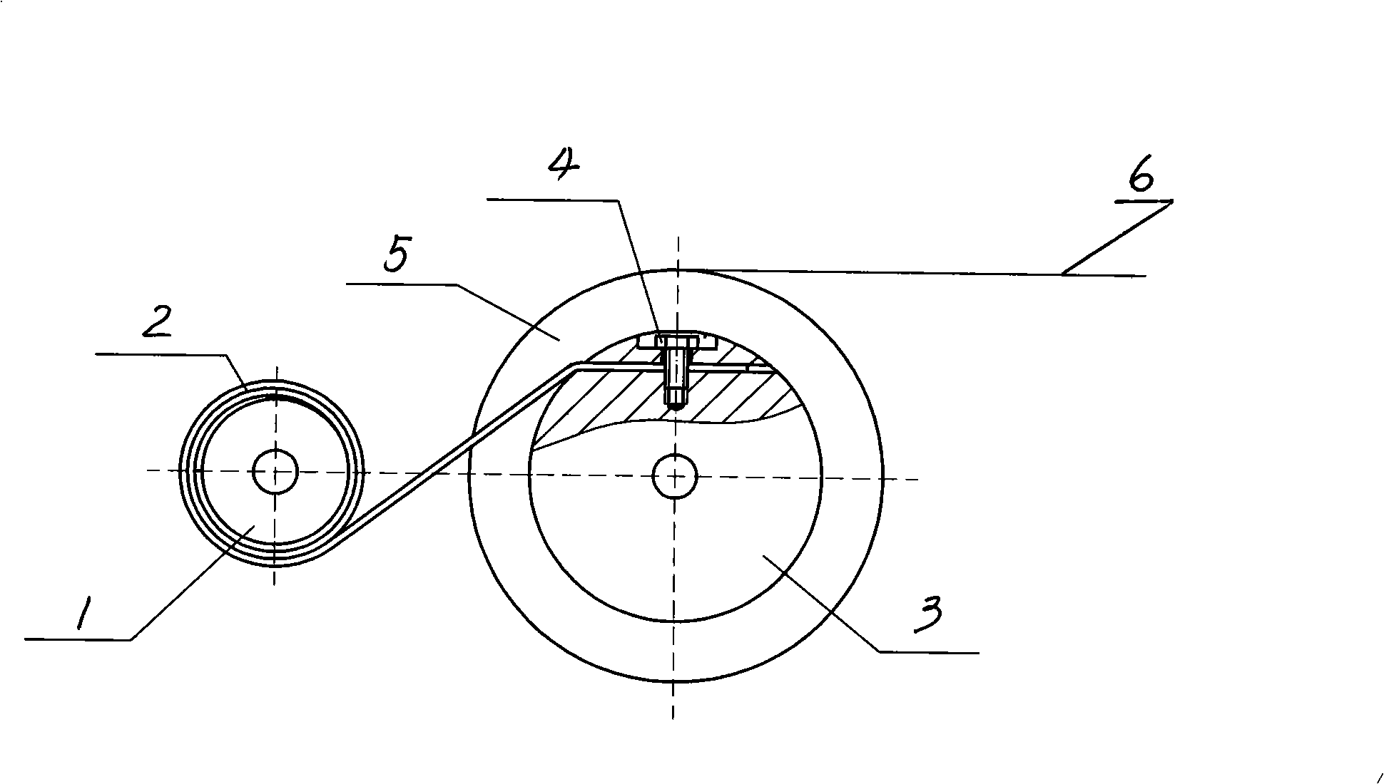
[0009] The present invention comprises a driven wheel 1, a retracting wheel 3 and an output wheel 5, one end of the constant force spring 2 is wrapped on the driven wheel 1, and the other end of the constant force spring 2 is fixed and rolled back on the retracting wheel 3; the output wheel 5 and The retracting wheel 3 is fixedly connected and coaxial; the diameter of the retracting wheel is larger than that of the driven wheel.

[0010] The working principle of the present invention: put the formed constant force spring on a driven wheel, fix one end of the constant force spring on the retracting wheel with a fixing bolt, and set an output wheel coaxially with the retracting wheel, and the retracting wheel The wheel is fixedly connected with the output wheel, and the output wheel is wound with a rope. When the rope is pulled out, the output wheel drives t...


PUM


Abstract

The invention discloses a back-scrolling type constant-force spring mechanism, comprising a driven wheel, a scrolling wheel and an output wheel, wherein, one end of a constant-force spring is scrolled and sleeved on the driven wheel, while the other end of the constant-force spring is fixed and back scrolled on the scrolling wheel, and the output wheel and the scrolling wheel are fixedly connected and are coaxial. The rectilinear motion of the constant-force spring is changed into the rotation motion through back scrolling the constant-force spring on the scrolling wheel. The constant-force spring is back scrolled on a scrolling wheel with a relatively large diameter, when an operating stroke is longer, a torque generated by the constant-force spring during the rotating process is maintained constant, and then the torque generated by the constant-force spring is changed into pulling force, so the generated pulling force is also maintained constant.

Description

Technical field [0001] The invention discloses a constant force spring mechanism. Background technique [0002] At present, the constant force springs used in various balance devices are directly pulled or pushed away to make a linear motion, so that the constant force springs output thrust or pull force. Its disadvantage is that when the working stroke is long, the change of thrust or pulling force is relatively large, and it is difficult to meet the requirement of constant force. Contents of the invention [0003] The purpose of the present invention is to provide a constant force spring mechanism with longer working stroke and less tension variation. [0004] The invention includes a driven wheel, a retracting wheel and an output wheel. One end of the constant force spring is wrapped around the driven wheel, and the other end of the constant force spring is fixed and rolled back on the retracting wheel; the output wheel is fixedly connected with the retracting wheel, a...

Claims


Application Information

Patent Timeline
Patent Type & Authority Applications(China)
IPC IPC(8): B65H75/34B65H75/48
Inventor 陈建礼
Owner SHANGHAI XIELI SPRING
Learn More