Method for bending metal wire comb-like form binding element

A technology of metal wire and components, applied in the direction of binding, application, folders, etc., to achieve the effect of stabilizing the printing material and avoiding lateral force

Inactive Publication Date: 2003-12-17
HEIDELBERGER DRUCKMASCHINEN AG
View PDF2 Cites 0 Cited by
  • Summary
  • Abstract
  • Description
  • Claims
  • Application Information

AI Technical Summary

Problems solved by technology

For bending, forming rollers with a defined diameter are used, so that only wire binding elements can be produced with unchangeable loop spacing and loop length

Method used


Image

  • Method for bending metal wire comb-like form binding element
  • Method for bending metal wire comb-like form binding element
  • Method for bending metal wire comb-like form binding element

Examples


Embodiment Construction

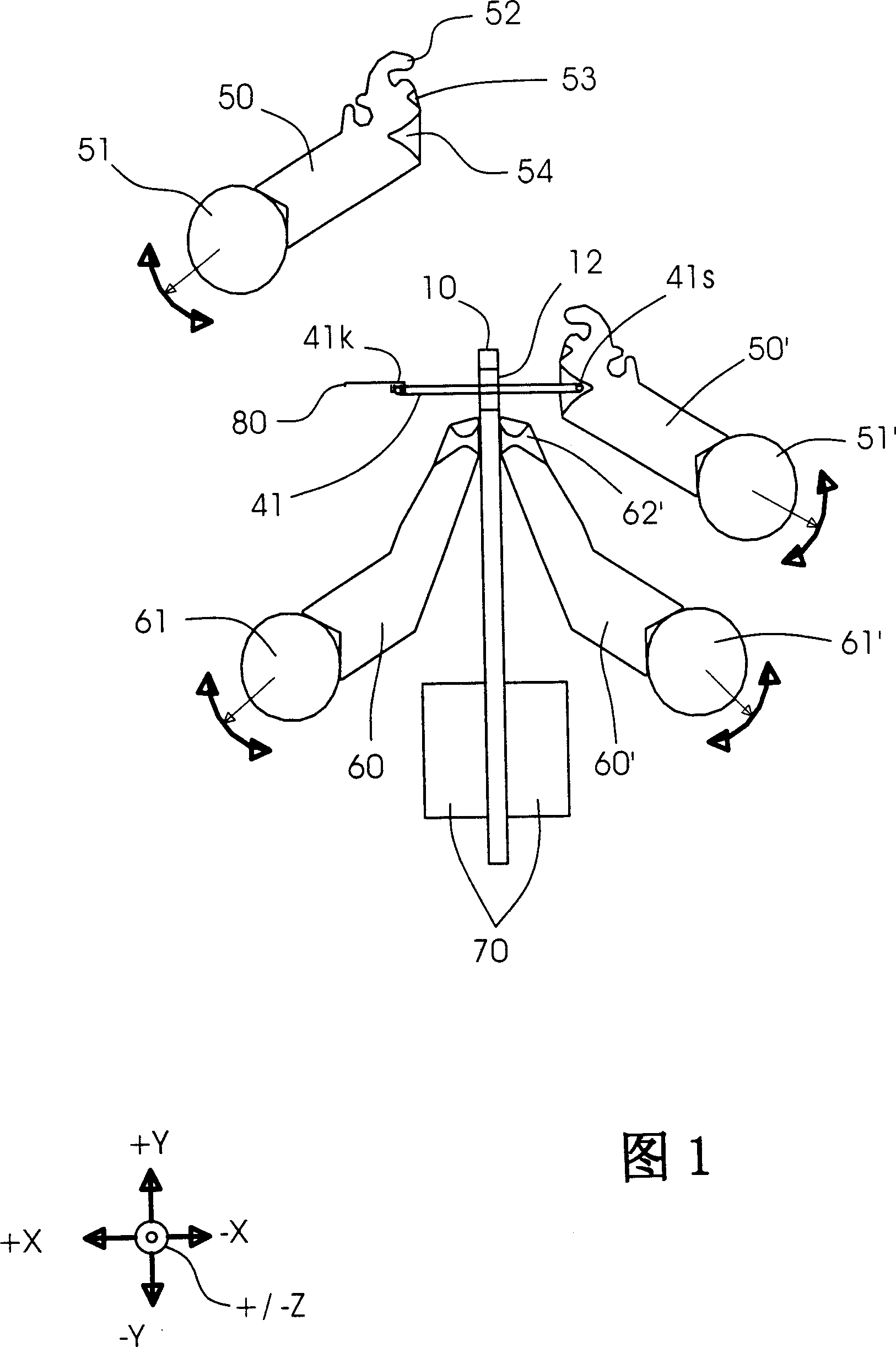
[0044] Fig. 1 shows the overall structure of the device of the present invention, and for simplicity of description, only the main components of the present invention are shown or described. Other drives and / or guides and electrical / electronic circuits which are generally known and required for the operation of the device are not shown here or are only described in general form.

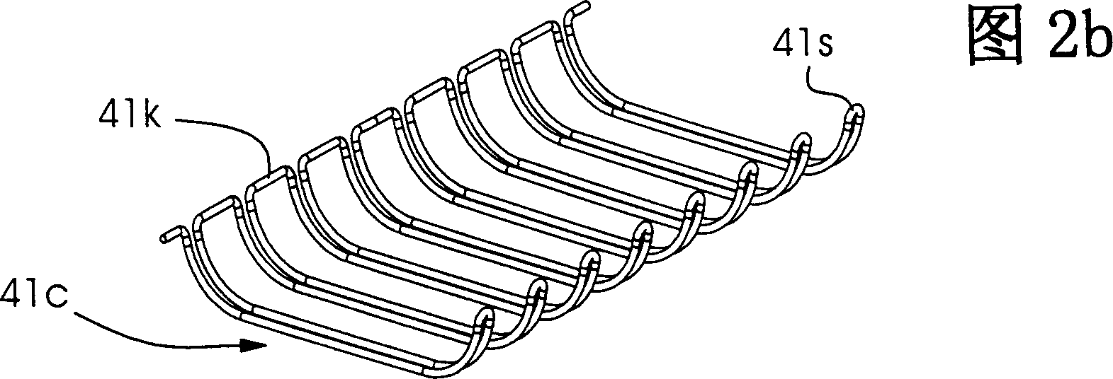
[0045] The device of the present invention mainly includes a pair of C-shaped shapers 50, 50' and a pair of O-shaped shapers. Shape 41c, the O-shaped shaper bends the return-bent wire binding element 41 bent into a C-shape 41c into a closed O-shape 41o for loosely binding the sheet-like printing materials 11 into a booklet 10 .

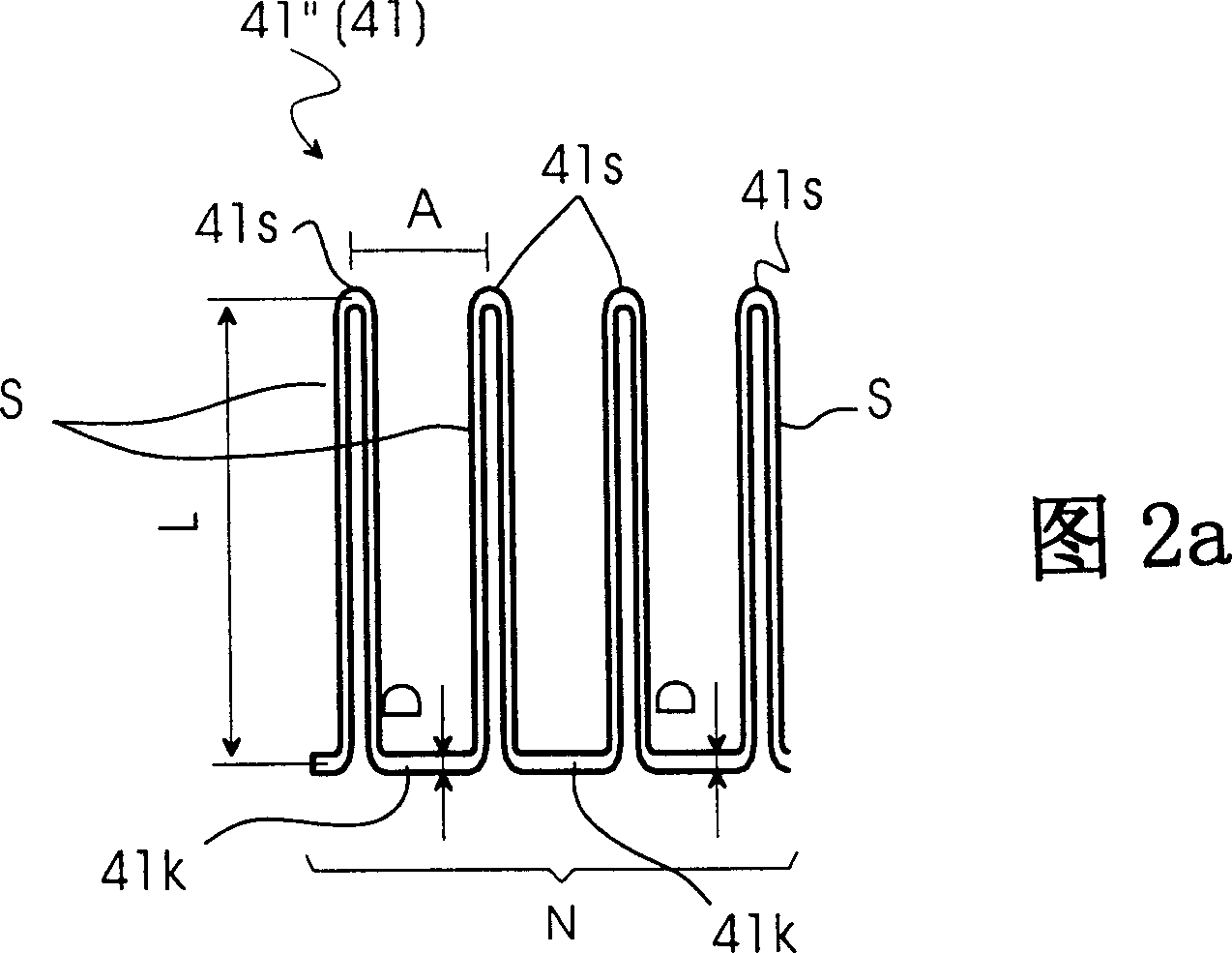
[0046] The sheet-shaped printing material 11 has a plurality of holes 12, and the outer edges of the holes of a stack of sheet-shaped printing materials 11 are identical, one above the other to form a substantially straight path for the return S of the flat wire binding elem...


PUM


Abstract

Device for loosely binding printed sheets to form booklets (10) using a loop-like wire binding element (41) comprises two C-shaping devices (50, 50') and two O-shaping devices (60, 60'). The C-shaping devices are positioned so that the initially flat wire binding element is bent into a C-shape. The O-shaping devices are positioned so that the C-shaped wire binding element is bent into a closed shape.

Description

technical field [0001] The present invention relates to an apparatus and method for bending wire binding elements used in wire comb binding. Background technique [0002] So-called Wire-O TM Method for making booklets from wire binding elements (registered trademark). [0003] A Wire-O wire binding element is defined as a mutually parallel spaced return bent wire having a return length L, a return spacing A and a wire diameter D as shown in Figure 2a, shaped into a Wire by means of a suitable closing device -O ring. [0004] Here, the binding device used in the above-mentioned patent application is constructed in such a way that it is possible to process preformed Wire-O-binding elements having different loop spacings and lengths. In this case, the preformed wire-O-binding element consists of semicircles, viewed from the side, each forming two interconnected C-shaped or ω-shaped structures. After the wire binding element has penetrated the hole in the sheet-like printing...

Claims


Application Information

Patent Timeline
Patent Type & Authority Applications(China)
IPC IPC(8): B42F13/16B21F45/16B42B5/08B42B5/10B65H37/04
CPCB42B5/10B42B5/103B21F45/16
Inventor 费迪南德·富克斯哈特穆特·罗伊施弗里茨·维特汉斯-彼得·维尔舒姆
Owner HEIDELBERGER DRUCKMASCHINEN AG
Why Eureka
Try Eureka