Rarefaction air condensing trapping device with liquid nitrogen suction refrigeration

A technology of liquefied air and liquid nitrogen, which is applied in the field of capture devices, can solve the problems of difficult to achieve refrigeration temperature, high cost, poor operability, etc., and achieve the problem of heat transfer and mass transfer of surface characteristics, low cost and simple operation Effect

Inactive Publication Date: 2008-12-10
HARBIN INST OF TECH
View PDF0 Cites 15 Cited by
  • Summary
  • Abstract
  • Description
  • Claims
  • Application Information

AI Technical Summary

Problems solved by technology

[0003] In order to solve the problems of high cost, poor operability and difficulty in achieving the required refrigeration temperature in the existing r

Method used


Image

  • Rarefaction air condensing trapping device with liquid nitrogen suction refrigeration
  • Rarefaction air condensing trapping device with liquid nitrogen suction refrigeration

Examples


specific Embodiment approach 1

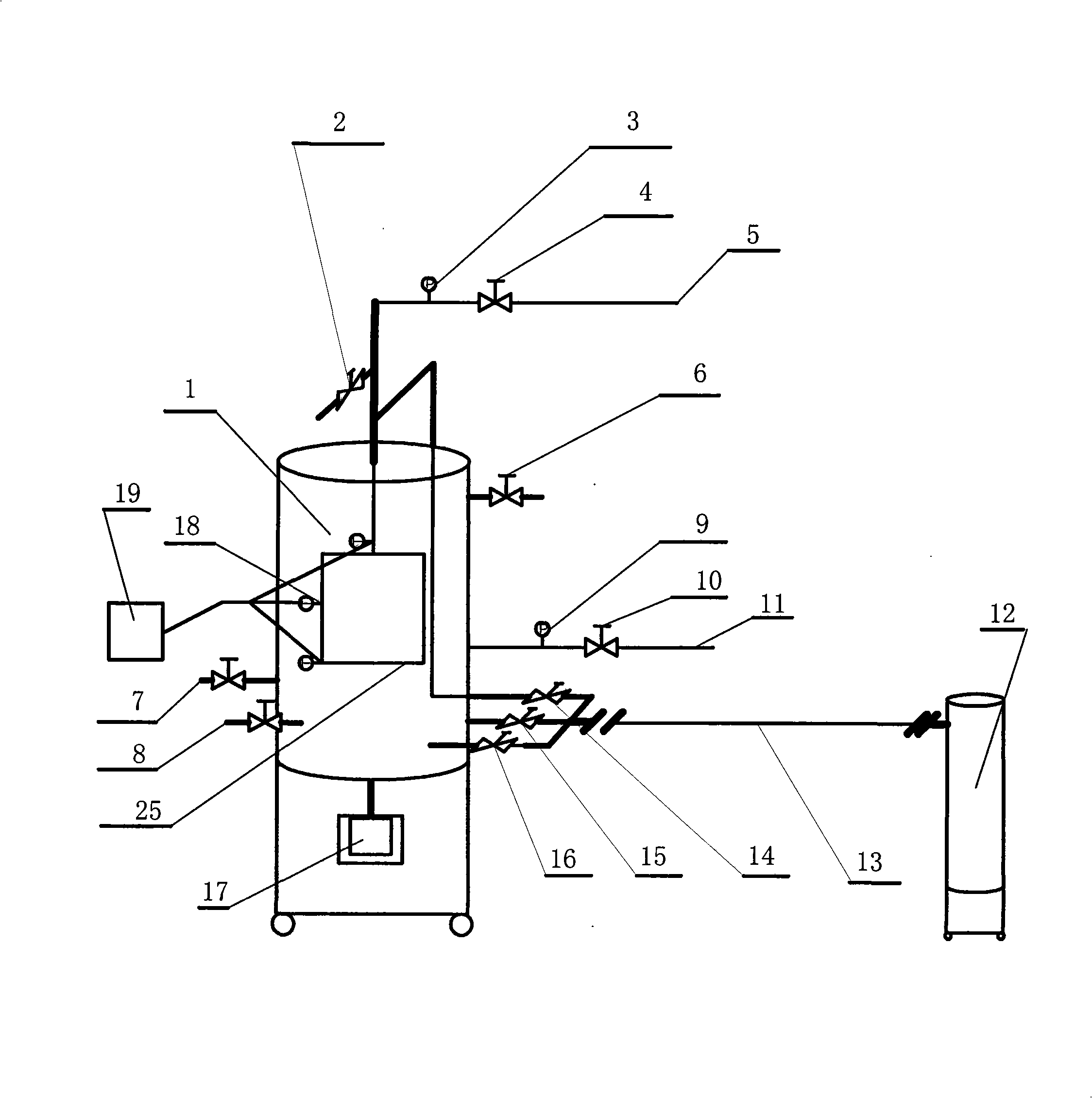
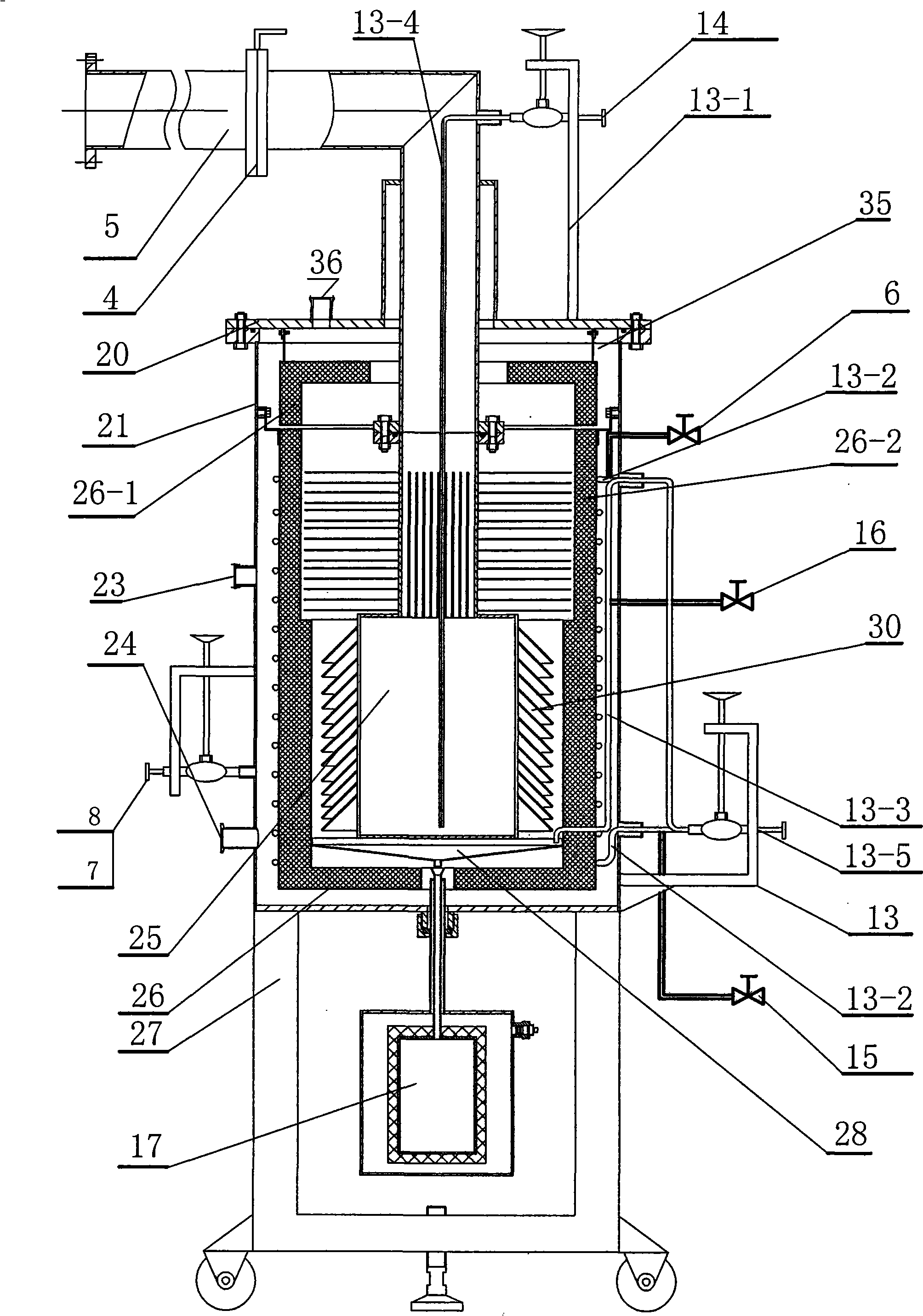
[0007] Specific implementation mode one: combine figure 1 with figure 2 Describe this embodiment. The liquid nitrogen pumping refrigeration rare air condensation trapping device in this embodiment includes a bracket assembly 27, a condensation trapping tank 1, a data acquisition module 19, a nickel-chromium-gold-iron thermocouple 18, and a nitrogen extraction Pipe 5, air extraction pipe 11, liquid nitrogen delivery pipe assembly 13, liquid nitrogen Dewar 12, liquefied air collection Dewar 17, liquefied air collection plate 28, the condensation trapping tank 1 is installed on the bracket assembly 27 The upper end; the condensation trapping tank body 1 includes an outer barrel 21, an outer barrel cover 20, a cold screen assembly 26, and a liquid nitrogen chamber 25. The cold screen assembly 26 is installed in the outer barrel 21, and the outer barrel cover 20 covers the outer barrel 21 and is airtightly connected with the upper end of the outer barrel 21, the cold shield assem...

specific Embodiment approach 2

[0009] Specific implementation mode two: combination figure 1 with figure 2 To describe this embodiment, the outer tub 21 in this embodiment is provided with a first sensor interface 23 , and the outer tub lid 20 is also provided with a second sensor interface 36 . This design makes it easy to install the sensor. Other components and connections are the same as those in the first embodiment.

specific Embodiment approach 3

[0010] Specific implementation mode three: combination figure 1 with figure 2 To illustrate this embodiment, the liquid nitrogen delivery pipe assembly 13 in this embodiment is composed of a straight pipe 13-4, a first pipe 13-1, a second pipe 13-2, a third pipe 13-3, an overall Pipeline 13-5, needle valve 14, cold screen valve 15, cavity pre-cooling valve 16, the main pipeline 13-5 is connected with the first pipeline 13-1, the second pipeline 13-2, and the third pipeline respectively. The pipeline 13-3 is connected, the first pipeline 13-1 is provided with a needle valve 14, the second pipeline 13-2 is provided with a cold screen valve 15, and the third pipeline 13-3 is provided with a cavity precooling valve 16. The straight pipe 13-4 communicates with the first pipeline 13-1, the second pipeline 13-2 is wound on the outer surface of the cold screen assembly 26, and the third pipeline 13-3 connects with the liquefied air collecting Dewar 17 connected. The liquid nitroge...


PUM


Abstract

A condensation trapping apparatus used for pumping and cooling rarefied air by liquid nitrogen relates to a trapping apparatus. The invention solves the problems of high cost, poor operability and being hard to realize needed cooling temperature existed in the existing rarefied air condensation trapping apparatus. A cold shield assembly (26) is arranged in an outer barrel (21); a liquid nitrogen chamber (25) is arranged at the bottom part of the cold shield assembly (26); a liquid air collecting disk (28) is arranged in the cold shield assembly (26) and is arranged below the liquid nitrogen chamber (25); a liquid air collecting Dewar (17) is arranged in a bracket assembly (27) and is communicated with the liquid air collecting disk (28) above the liquid air collecting Dewar (17); one end of a nitrogen extraction tube (5) penetrates a heat preservation cover (26-1) of the cold shield assembly (26) and is communicated with the upper end of the liquid nitrogen chamber (25); a liquid nitrogen conveying pipe assembly (13) is arranged on the cold shield assembly (26). The trapping apparatus of the invention has the advantages of low cost, high operability and simple operation; besides, the trapping apparatus can provide a cold source with low temperature of 55 K and even lower temperature and can effectively realize to trap the air over 2000Pa.

Description

technical field [0001] The invention relates to a trapping device, in particular to a liquid nitrogen suction refrigeration rarefied air condensation trapping device. Background technique [0002] The air-breathing propulsion is used as the power device of the near-space vehicle. Obtaining the working fluid and realizing the high-pressure ratio pressurization of the rarefied air are the core technical challenges it faces. The low-temperature cold source is used to condense and capture the atmosphere in the adjacent space and use the low-temperature liquid The pump is pressurized to 10MPa, which not only solves the working fluid problem of the air-breathing propulsion system, but also solves the key technical problem of high-pressure ratio boosting. The core problem of the high-pressure ratio supercharging system is the adsorption and capture of rarefied air. The phase change temperature of the air varies with the altitude. The atmospheric pressure at 20km is about 5000Pa, t...

Claims


Application Information

Patent Timeline
IPC IPC(8): B64D37/00
Inventor 姚战立鲍文蒲星星吕晓武
Owner HARBIN INST OF TECH
Why Eureka
Try Eureka