Image processing method, image processing apparatus, and image forming apparatus
An image processing and image technology, applied in character and pattern recognition, instrumentation, calculation, etc., can solve the problems of small number of feature points, insufficient guarantee, and reduced accuracy of feature quantity.
- Summary
- Abstract
- Description
- Claims
- Application Information
AI Technical Summary
Problems solved by technology
Method used
Image
Examples
Embodiment 1
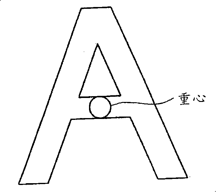
[0119] FIG. 12 is a schematic diagram showing the structure of the center-of-gravity calculation unit 2214 of the first embodiment. In Embodiment 1, the connected component threshold processing unit 2214b functions as the first connected component threshold processing unit 2214b1 and the second connected component threshold processing unit 2214b2, and the center-of-gravity calculation processing unit 2214c functions as the first center-of-gravity calculation processing unit 2214c1 and the second center-of-gravity calculation processing unit 2214c1. In the unit 2214c2, the center of gravity storage buffer 2214d serves as the first center of gravity storage buffer 2214d1 and the second center of gravity storage buffer 2214d2. The center of gravity calculation unit 2214 in other embodiments performs threshold judgment based on the first threshold (for example, 30, 100) different from the first connected component threshold and the second connected component threshold, performs cen...
Embodiment 2
[0122] FIG. 13 is an explanatory diagram showing an example of an input document image. Generally, there are various formats of manuscripts to be input, but there are few cases where the same characters exist in the entire manuscript, and there are many cases where no characters exist in the top, bottom, left, and right end regions of the manuscript. For example, as shown in FIG. 13 , when the lower limit of the threshold judgment is also set to 100, since the noise is within the range of the threshold judgment, it becomes the object of center of gravity calculation. Also, when the number of pixels of connected components of characters existing in the central region of the document image is 100 or less (for example, the number of pixels of point i), it is not subject to center of gravity calculation. As a result, there is a possibility that the accuracy of the calculated center of gravity may decrease.
[0123] Therefore, in the second embodiment, by dividing the document ima...
Embodiment 3
[0142] Example 3
[0143] Figure 23 It is a flowchart showing the procedure of the processing of the feature amount calculating section 222 of the third embodiment. In the feature calculation unit 222 of the third embodiment, the pixel block setting unit 2220 sets a pixel block composed of one or more pixels of the image, and sets the mask length of the set pixel block (S501 ). The feature amount calculation unit 222 uses one of the feature points extracted by the pixel block setting unit 2220 as a feature point of interest, and sets the surrounding 8 pixel blocks centered on the pixel block containing the feature point of interest as the “peripheral area”. ”, output the data including the set pixel block, mask length and surrounding area to the nearby point extraction unit 2221.
[0144]In feature quantity calculation section 222, nearby point extraction section 2221 receives the data output from pixel block setting section 2220, and extracts nearby feature points within ...
PUM
 Abstract
Description
Claims
Application Information
 - R&D
- Intellectual Property
- Life Sciences
- Materials
- Tech Scout
- Unparalleled Data Quality
- Higher Quality Content
- 60% Fewer Hallucinations
Browse by: Latest US Patents, China's latest patents, Technical Efficacy Thesaurus, Application Domain, Technology Topic, Popular Technical Reports.
© 2025 PatSnap. All rights reserved.Legal|Privacy policy|Modern Slavery Act Transparency Statement|Sitemap|About US| Contact US: help@patsnap.com


