Fuel injector having a directly actuable injection valve element

A technology of fuel injectors and injection valves, which is applied to fuel injection devices, fuel injection valves driven by fluid pressure, engine components, etc., and can solve problems such as injection quantity fluctuations

Inactive Publication Date: 2008-12-24
ROBERT BOSCH GMBH
View PDF1 Cites 16 Cited by
  • Summary
  • Abstract
  • Description
  • Claims
  • Application Information

AI Technical Summary

Problems solved by technology

This vibration leads to fluctuations in the injection quantity because the throttle cross-section of the nozzle needle on the nozzle needle sealing seat changes

Method used


Image

  • Fuel injector having a directly actuable injection valve element
  • Fuel injector having a directly actuable injection valve element

Examples


Embodiment Construction

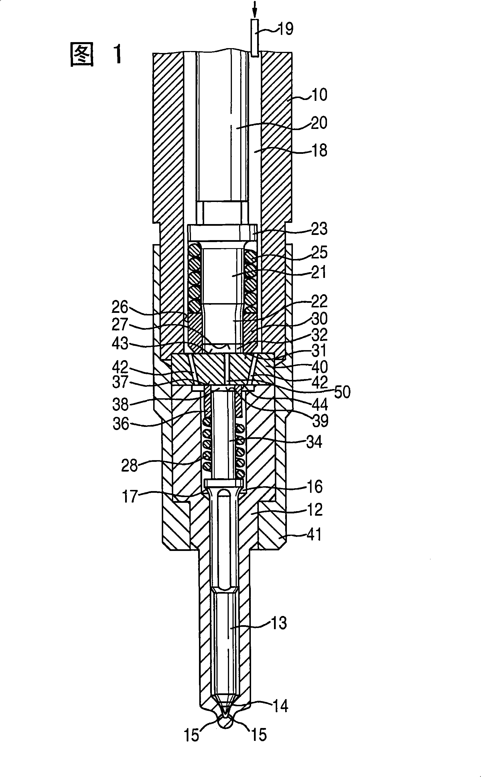
[0012] The fuel injector shown in FIG. 1 has an injector housing 10 with an injection valve element which projects with a nozzle body 12 into a combustion chamber of the internal combustion engine. A nozzle needle 13 is guided axially displaceably in the nozzle body 12 . At the tip of the nozzle needle 13, a nozzle needle seal seat 14 is formed on the nozzle body 12, behind which the nozzle 15, which is formed in the nozzle body 12 and protrudes into the combustion chamber, is arranged in the injection direction. . A nozzle needle pressure chamber 16 , in which a nozzle needle-side pressure shoulder 17 formed on the nozzle needle 13 is situated, is arranged upstream of the nozzle needle sealing seat 14 in the injection valve element in the spraying direction.

[0013] The injector housing 10 has a pressure chamber 18 which is connected via a connection 19 to a high-pressure system (not shown), for example a common rail system of a diesel injection system. A piezoelectric act...


PUM


Abstract

A fuel injector for an internal combustion engine is proposed having a directly actuable injection valve element. The fuel injector has a nozzle needle (13), axially guided in a nozzle body (12), and an actuator (20) accommodated in an injector housing (10), wherein the nozzle needle (13) is connected to a coupling piston (34) on the nozzle-needle side and the actuator (20) is connected to a coupling piston (21) on the actuator side. The coupling piston (21) on the actuator side acts on a coupling space (32) and the coupling piston (35) on the nozzle-needle side acts on a control space (38), wherein the nozzle needle (13) is lifted from a nozzle-needle sealing seat (14) as a function of the pressure in the control space (38).; Provided between injector housing (10) and nozzle body (12) is an intermediate plate (40) having a passage (50) which hydraulically connects the coupling space (32) to the control space (38). The passage (50) contains a hydraulic choke (51) which has at least two sections (52, 53) having different cross sections of flow, wherein the section (52) having the smaller cross section of flow faces the coupling space (32) and the section (53) having the larger cross section of flow faces the control space (38).

Description

technical field [0001] The invention relates to a fuel injector for an internal combustion engine according to the preamble of claim 1 . Background technique [0002] DE 10 2004 005 452 A1 describes a fuel injector with a directly actuatable injection valve element and the opening of the nozzle needle by means of a single-stage shift of the actuator stroke using a pulled actuator. A coupling piston on the actuator side, actuated by the actuator, acts on a coupling chamber and a coupling piston connected to the nozzle needle acts on a control chamber. The coupler chamber is hydraulically connected to the control chamber via a channel. In this case, the channel is arranged in an intermediate disk which is arranged between the injector body and the nozzle body. [0003] When the actuator is actuated, high accelerations and corresponding vibrations of the actuator are caused at the end of the stroke of the actuator, which vibrations are transmitted via the hydraulic chamber to...

Claims


Application Information

Patent Timeline
Patent Type & Authority Applications(China)
IPC IPC(8): F02M47/02F02M51/06F02M63/00
CPCF02M47/02F02M51/0603F02M2547/001
Inventor W·施特克莱因T·保尔C·库纳特
Owner ROBERT BOSCH GMBH
Why Eureka
Try Eureka