
Image display control apparatus and method

A technology for image display and control equipment, which is applied in image communication, image data processing, graphics and image conversion, etc., and can solve problems such as inability to effectively confirm areas

Active Publication Date: 2009-01-07
CANON KK
View PDF2 Cites 7 Cited by
  • Summary
  • Abstract
  • Description
  • Claims
  • Application Information

AI Technical Summary

Problems solved by technology

Effective confirmation of regions cannot be achieved when those regions are confirmed individually without considering the correlation between regions as in the related art

Method used


Image

  • Image display control apparatus and method
  • Image display control apparatus and method
  • Image display control apparatus and method

Examples


Embodiment Construction

[0039] Hereinafter, exemplary embodiments of the present invention will be described in detail with reference to the drawings.

[0040] Note that the following exemplary embodiment is only an example for realizing the present invention, and it can be appropriately modified or changed according to the respective structures and various conditions of the devices to which the present invention is applied. Therefore, the present invention is by no means limited to the following exemplary embodiments.

[0041] The structure of a digital camera

[0042] (a) Appearance

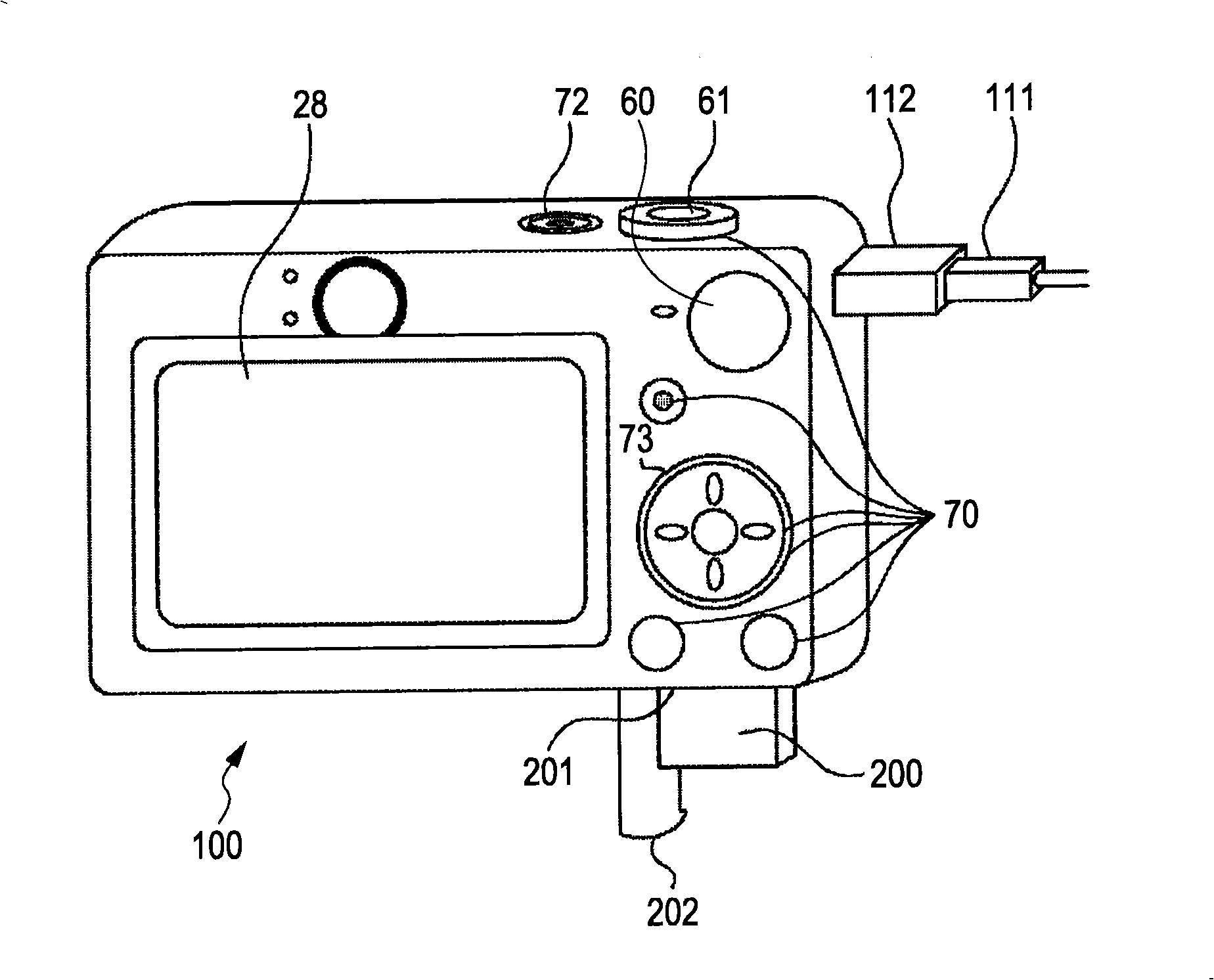
[0043] Figure 1A It is an external view of a digital camera as an example of an image display control device according to an exemplary embodiment of the present invention. in Figure 1A In, the display unit 28 displays images and various information items. The power switch 72 switches the power supply on and off. Reference numeral 61 denotes a shutter button. The zoom lever is set outside the shutter button 61. The ...


PUM


Abstract

The invention relates to an image display control apparatus and method. A degree of overlapping between separately obtained regions of respective parts of an image is determined. When the degree of overlapping is greater than a defined value, only one of the obtained regions, or both the regions, or a region including both the regions is selected. When the degree of overlapping is less than the defined value, the separately obtained regions of respective parts of the image are separately selected. The image is displayed while reflecting a result of the selection.

Description

Technical field [0001] The present invention relates to an image display control device and method for displaying images, and also relates to a recording medium on which a program is recorded. Background technique [0002] Recently, a technique of displaying frames for various purposes has been proposed, in which each frame corresponds to an image area. For example, an in-focus frame is used in an overlapping relationship with the image and / or in an enlarged size to indicate the image area that has been selected for focus adjustment when the image is taken, and is used to indicate that the face has been detected by image analysis. The face frame of the area. [0003] For example, Japanese Patent Application Publication No. 2005-295418 describes the following technique. The subject and the focus frame are displayed in an overlapping relationship when shooting, and the area of ​​the focus frame in the image is displayed in an enlarged size when the image is reproduced. In addition,...

Claims


Application Information

Patent Timeline
Patent Type & Authority Applications(China)
IPC IPC(8): H04N5/232G06K9/00G06T3/40
CPCH04N5/23293H04N5/23219H04N23/61H04N23/611H04N23/635
Inventor 须藤幸司丹羽智弓吉田宣和
Owner CANON KK
Learn More