
Method and apparatus for selectively displaying measurement result and corresponding images

a technology of image display and measurement results, applied in the direction of nucleotide libraries, instruments, material analysis, etc., can solve the problem of difficulty in finding a spot position corresponding to a measuremen

Inactive Publication Date: 2004-10-05
FUJIFILM CORP +1
View PDF8 Cites 3 Cited by
  • Summary
  • Abstract
  • Description
  • Claims
  • Application Information

AI Technical Summary

Benefits of technology

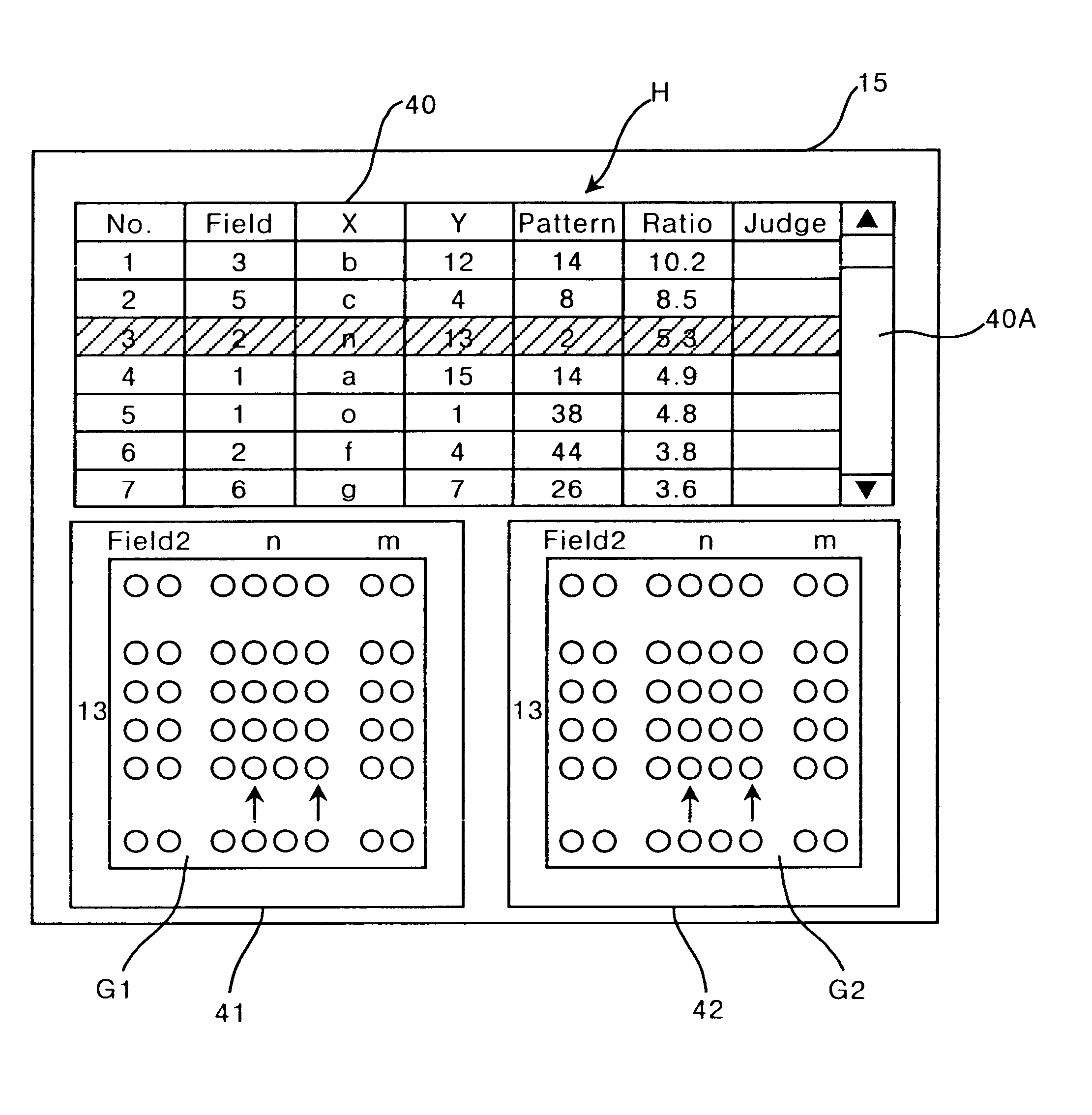
According to the image display method of the first aspect of the present invention, the operator can select, in step (b), a desired list from the measurement result table displayed in step (a). In response to the selection, the portions containing the measurement spots in the at least two images corresponding to the selected list are automatically displayed in step (c). Therefore, the operator can efficiently confirm the measurement results referring to the images (the above portions) of the corresponding measurement spots.
According to the image display method and apparatus of the second aspect of the present invention, the operator can select, in step (b), one of the plurality of measurement spots where the desired measured result is obtained in one of the at least two images. In response to the selection, lists showing the measurement result corresponding to the selected measurement spot in the measurement result table are automatically displayed in step (c). Therefore, the operator can efficiently confirm the measurement results referring to the images (the above portions) of the corresponding measurement spots.

Problems solved by technology

Therefore, it is very difficult to find a spot position corresponding to a measurement result, by a visual search of the displayed images.

Method used


Image

  • Method and apparatus for selectively displaying measurement result and corresponding images
  • Method and apparatus for selectively displaying measurement result and corresponding images
  • Method and apparatus for selectively displaying measurement result and corresponding images

Examples


Embodiment Construction

Embodiments of the present invention are explained in detail below with reference to drawings.

(1) Array Chip

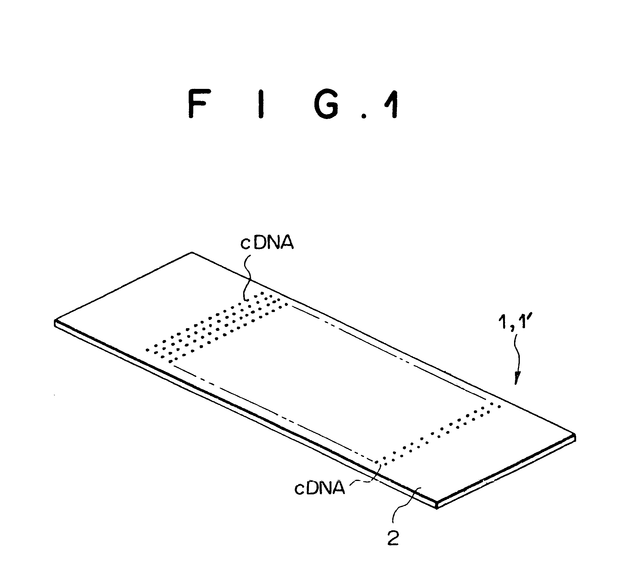
FIG. 1 is a diagram illustrating an array chip used in an embodiment of the present invention. The array chip 1 or 1' illustrated in FIG. 1 is formed by arranging a plurality of different, known cDNAs (as specific binding materials) at a plurality of predetermined positions on a support 2, which is, for example, a membrane filter, a slide glass, or the like. The plurality of cDNAs correspond to a plurality of different DNAs of which base sequences are already decoded, and the spot positions of the respective cDNAs on the support 2 are predetermined by the manufacturer of each array chip. Two array chips 1 and 1' each having the construction of FIG. 1 are provided, and are respectively hybridized with two different cDNAs (as a material derived from biological origin). The two different cDNAs are respectively derived from different samples A and B, and are labeled with a fluores...


PUM


Abstract

An image display apparatus contains a display unit which displays information. A table displaying unit controls the display unit so as to display a measurement result table including a plurality of lists each of which is obtained from at least two corresponding measurement spots in at least two images, where the at least two corresponding measurement spots belong to the at least two images, respectively, so that the at least two images each include a plurality of measurement spots which respectively correspond to a plurality of measurement spots in every other one of the at least two images. An instruction receiving unit receives an instruction to select one of the plurality of lists in the measurement result table. An image display control unit controls the display unit so as to selectively display a portion of each of the at least two images so that the portion contains one of the plurality of measurement spots which corresponds to the one of the plurality of lists.

Description

1. Field of the InventionThe present invention relates to an image display method and an image display apparatus for displaying, using a display unit such as a CRT, at least one image and a table which indicates results of measurement performed in the image in the form of a plurality of lists. For example, the image is obtained by detecting a material of biological origin on an array chip which is provided for DNA analysis, immunological analysis, or the like.2. Description of the Related ArtRecent development in gene engineering technology has been remarkable. Such development in the gene engineering technology is enabling, for example, the human genome project which is attempting to unravel all of the base sequences of the human genome, although the total number of genes in the human genome are considered to be in the order of hundreds of thousands. In addition, in order to clarify causes of various genetic diseases, research on DNA is progressing rapidly.On the other hand, variou...

Claims


Application Information

Patent Timeline
IPC IPC(8): G06T11/20C40B40/06
CPCG06T11/20B01J2219/00585B01J2219/00596B01J2219/00605B01J2219/00608B01J2219/00707B01J2219/00722C40B40/06B01J2219/00659
Inventor SHIBATA, HIROMIOGURA, NOBUHIKO
Owner FUJIFILM CORP
Learn More