
Method and System for Providing Power

Inactive Publication Date: 2007-11-01
CISCO TECH INC
View PDF28 Cites 4 Cited by
  • Summary
  • Abstract
  • Description
  • Claims
  • Application Information

AI Technical Summary

Benefits of technology

[0005] Embodiments of the invention may provide numerous technical advantages. Some, none, or all embodiments may benefit from the below described advantages. According to one embodiment, proper working of a backup power supply may be tested without manual intervention. This provides an efficient manner of confirming that uninterrupted power is available, without the conventional associated costs of manually bringing down a power supply to determine if the associated backup power supply would function properly. Further, in some embodiments, the primary power supply may be automatically turned on by a telecommunication switch and the backup power may be turned off by the telecommunication switch, allowing return to normal operating conditions without manual intervention.

Problems solved by technology

This testing procedure can be problematic because it requires hands-on attention by personnel to shut down the primary supply and to shut down the backup supply after the test is completed.
In addition, backup power supplies conventionally could not receive communications from the associated telecommunication switch, but could only provide one way status information from the power supply to the switch.

Method used


Image

  • Method and System for Providing Power
  • Method and System for Providing Power

Examples


Embodiment Construction

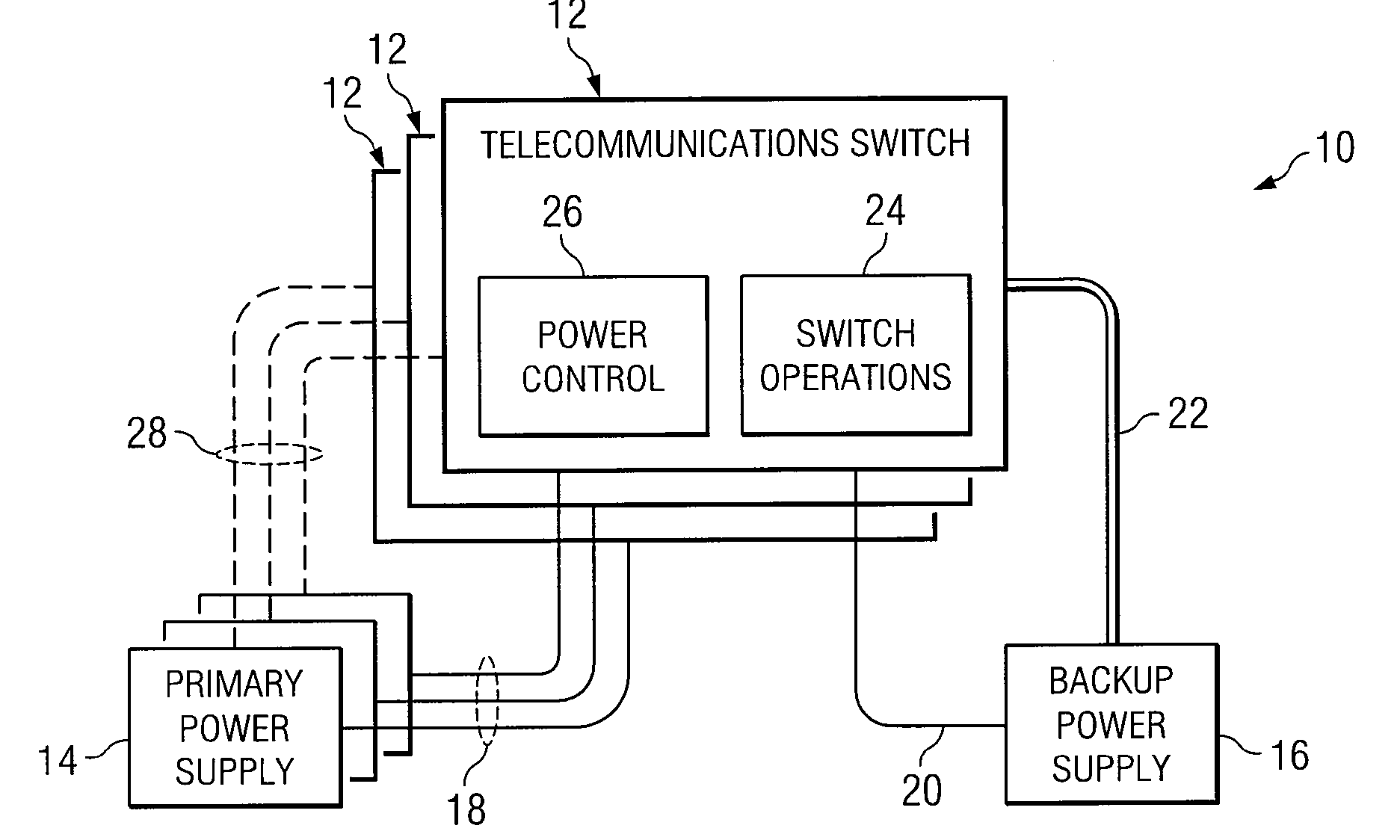
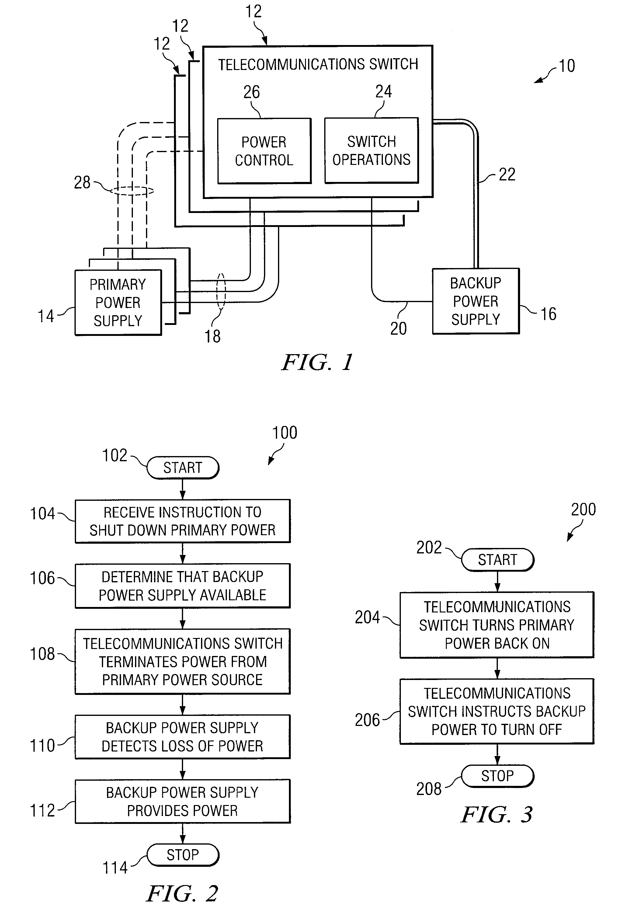
[0011] Example embodiments of the present invention and their advantages are best understood by referring to FIGS. 1 through 3 of the drawings, like numerals being used for like and corresponding parts of the various drawings.

[0012]FIG. 1 is a block diagram of a telecommunication system according to the teachings of the invention. Telecommunication system 10 includes a telecommunication switch 12, a primary power supply 14, and a backup power supply 16. Primary power supply is communicatively coupled to telecommunication switch 12 by a link 18, and backup power supply 16 is communicatively coupled to telecommunication switch 12 by a link 20. Links 18 and 20 provide power from the respective power supply 14, 16 to telecommunication switch 12, and links 18 and 20 may be in any suitable form operable to communicate the required power for telecommunication switch 12 from the respective power supply. Telecommunication system 10 also includes a communications channel 22 coupling backup p...


PUM


Abstract

According to one embodiment of the invention, a method for providing power includes providing a telecommunication switch coupled to a backup power supply by a communication path that allows communication of control information from the telecommunication switch to the backup power supply. The method also includes providing a primary power supply operable to provide power to the telecommunication switch and terminating, by the telecommunication switch, power to the telecommunication switch from the primary power supply.

Description

TECHNICAL FIELD OF THE INVENTION [0001] This invention relates generally to power supplies and more particularly to a method and system for providing power. BACKGROUND OF THE INVENTION [0002] Power supplies are used in association with telecommunication switches and other devices. It is commonplace for a redundant power supply to be utilized in conjunction with a telecommunication switch, or other device, in instances where it is important that the telecommunication switch provide continuous operation in the event of failure in the primary power supply. Conventionally, if the primary power supply fails, the redundant power supply turns on and provides power to the telecommunications switch. [0003] Conventionally, in order to detect the proper operation of the redundant power supply, the primary power supply was physically brought down, and operation of the backup power supply (also known as redundant power supply (RPS)) was examined. Further, the backup power supply would have to be...

Claims


Application Information

Patent Timeline
IPC IPC(8): H02J9/00
CPCH02J9/061H02J13/0003Y04S20/18Y02B90/228Y04S20/12Y02B90/222Y02B90/20H02J13/00036Y04S20/00
Inventor ZIMMERMAN, CRAIG A.BOONE, EARL W.CHERUKATT, VINOD
Owner CISCO TECH INC
Learn More