System and method for limiting robot work region

A work area, robot technology, applied in transmission systems, near-field transmission systems, control/regulation systems, etc., to solve problems such as displacement, virtual wall failure, etc.

Inactive Publication Date: 2009-01-14
ECOVACS ROBOTICS (SUZHOU ) CO LTD
View PDF0 Cites 18 Cited by
  • Summary
  • Abstract
  • Description
  • Claims
  • Application Information

AI Technical Summary

Problems solved by technology

However, since the robot only sends signals to one side, and the directional notch of the virtual wall generating device, the user may not necessarily face the robot transmitting or receiving signal side when placing it, causing the virtual wall to fail. In addition, when the robot is not on the virtual wall generating device When traveling in the direction of the notch, it is possible to collide with the virtual wall generating device and make it shift, and the user is required to place the virtual wall generating device in the corner.

Method used


Image

  • System and method for limiting robot work region

Examples


Embodiment 1

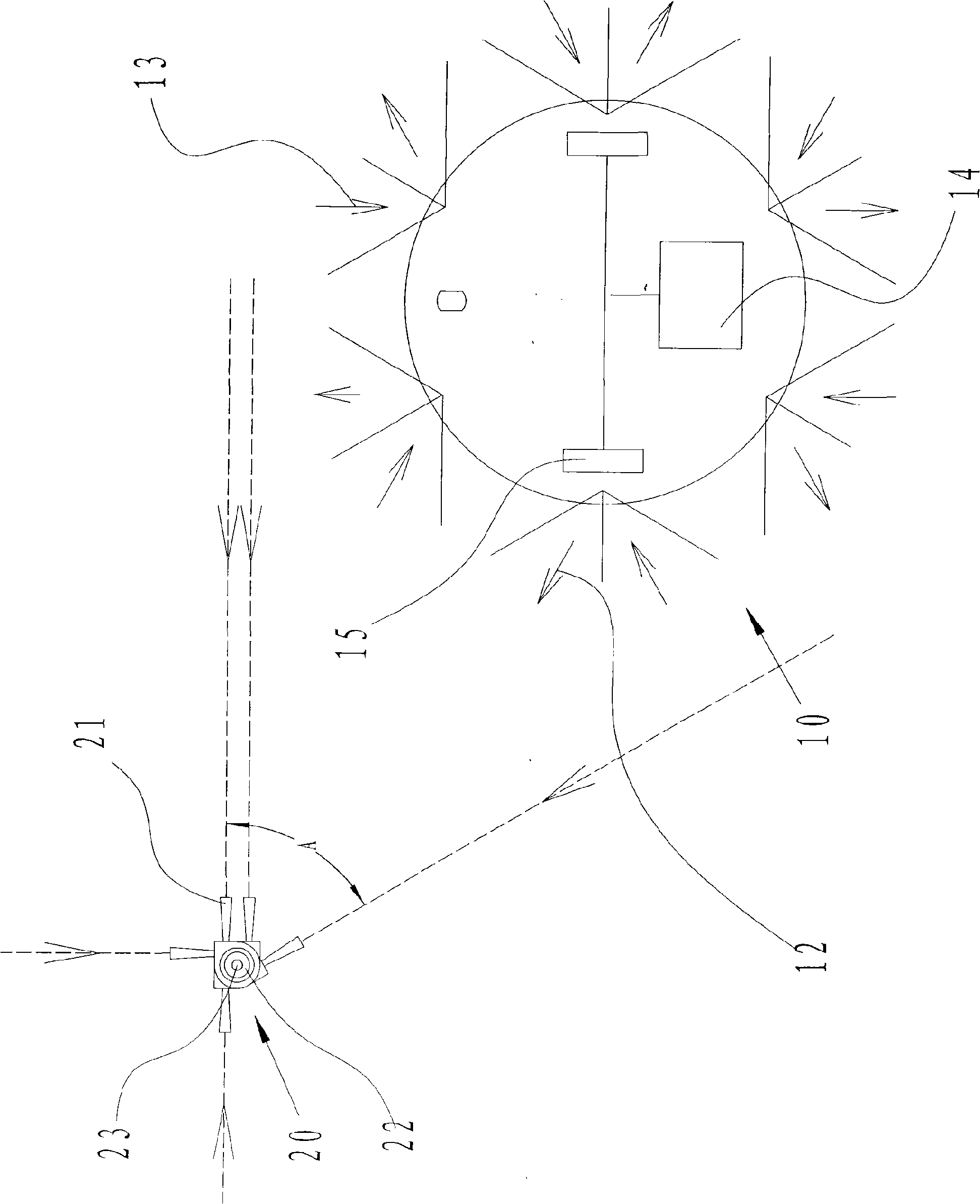
[0015] Referring to the accompanying drawing 1, the robot virtual wall system mainly includes a robot 10 and a transponder 20, wherein:

[0016] The robot 10 has a steering device 15, and has a control unit 14 connected to the steering device 15 for controlling the steering of the steering device 15, and has a first signal transmitting unit 12 for emitting a substantially omnidirectional signal. For signals, the first signal transmitting unit 12 is distributed on the side wall of the robot, and has a second signal receiving unit 13 for receiving substantially all-round signals.

[0017] The transponder 20 has a first signal receiver 21 for mainly receiving the first transmission signal 12 emitted by the robot in a restricted area, the restricted area forms a guided virtual disorientation 24, and has a second The signal transmitter 22 is used to transmit a substantially omnidirectional signal. When the first signal receiver 21 detects the signal transmitted by the first signal ...


PUM


Abstract

The invention relates to a system and a method for restricting working areas of robots. The system comprises: a movable robot, which comprises a first signal emitting unit, a second signal receiving unit and a control unit for controlling movement of the robot; and a portable responder, which comprises a first signal receiver mainly used for receiving a first emission signal emitted by the robot in a restricted area which forms a guided virtual disorientation, and the portable responder emits a second emission signal after the first emission signal is received by the first signal receiver. Then, once detecting the second emission signal, the robot detector avoids the virtual disorientation, and the control unit of the robot executes an algorithm which comprises robot turning or backing procedures until the detector cannot receive the first emission signal.

Description

technical field [0001] The present invention relates to a working area of ​​a robot, in particular to a system and method for defining a working area of ​​a robot. Background technique [0002] In the prior art, various systems are used to confine a robot to a specific physical space in order to perform certain tasks. For example, maintenance of turf, floor cleaning, inspection, transportation and entertainment require robots to operate within a certain limited range to perform the work. [0003] For example, a vacuuming robot working in a room may inadvertently run from one room to another before finishing vacuuming the first room. One solution is to confine the robot to the first room and physically prevent the robot from leaving the first room by closing all the doors. But in many houses, rooms are separated by open corridors, and doors or their physical barriers are not easily placed in the robot's exit path. Likewise, a customer may want the robot to work only in par...

Claims


Application Information

Patent Timeline
Patent Type & Authority Applications(China)
IPC IPC(8): G05D1/00H04B5/00
Inventor 汤进举郑德钦
Owner ECOVACS ROBOTICS (SUZHOU ) CO LTD
Why Eureka
Try Eureka