Clip for washing bottle

A bottle clip and clip technology, which is applied in the directions of cleaning hollow objects, cleaning methods and utensils, chemical instruments and methods, etc., can solve the problems of unfavorable transportation, increase the production cost of the bottle washer, and the shape of the bottle washer is huge, and saves money. Installation space, the effect of saving production costs

Inactive Publication Date: 2009-01-21
JIANGSU ASG PACKAGING MACHINERY GRP
View PDF0 Cites 20 Cited by
  • Summary
  • Abstract
  • Description
  • Claims
  • Application Information

AI Technical Summary

Problems solved by technology

Since the turning center point of this bottle rinsing device is not on the center line of the clamping bottle, the distance between the bottle and the center of the rotary table 11 becomes smaller after the bottle is turned over, and the distance between the bottle and

Method used


Image

  • Clip for washing bottle
  • Clip for washing bottle
  • Clip for washing bottle

Examples


Embodiment Construction

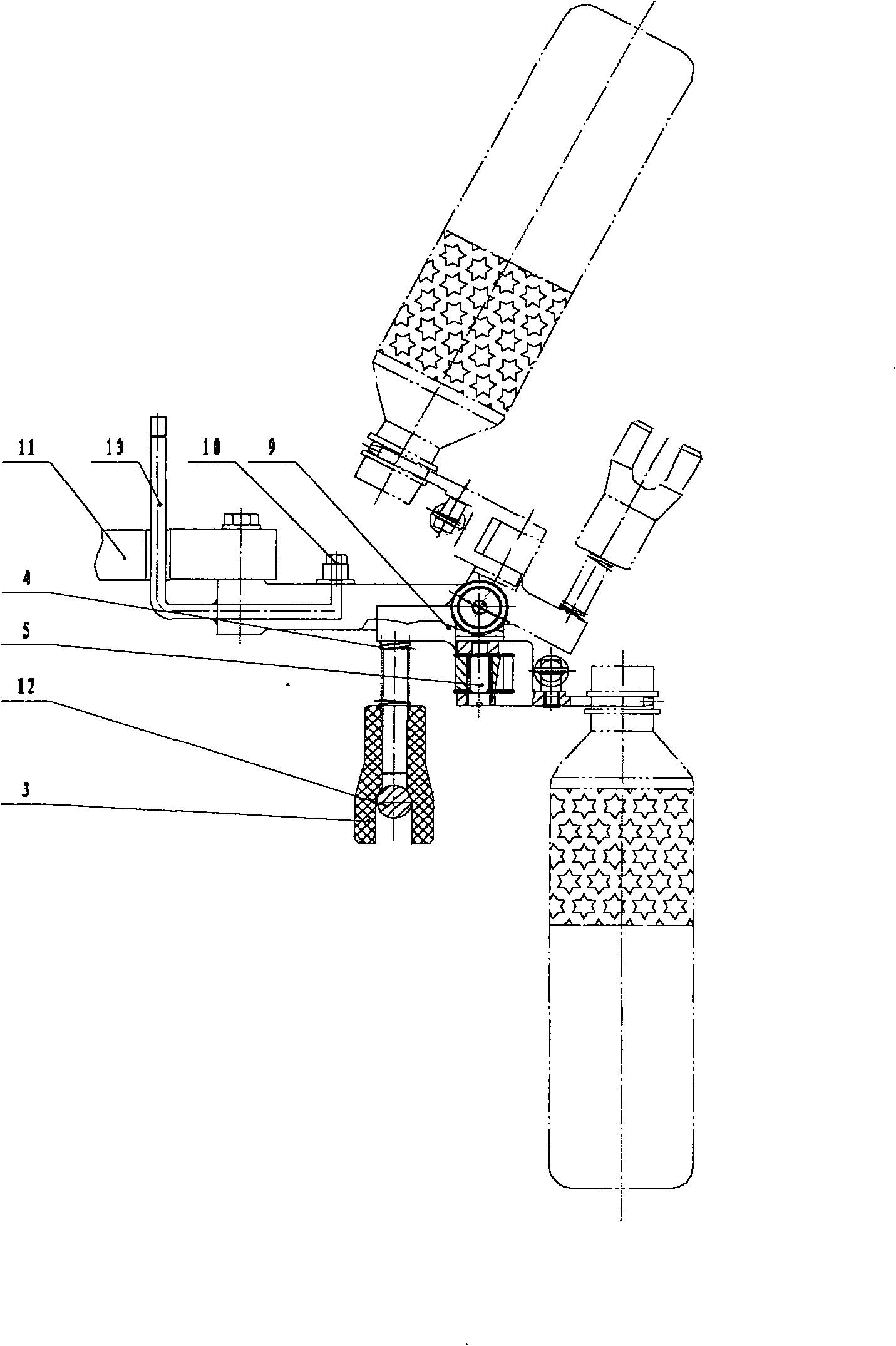
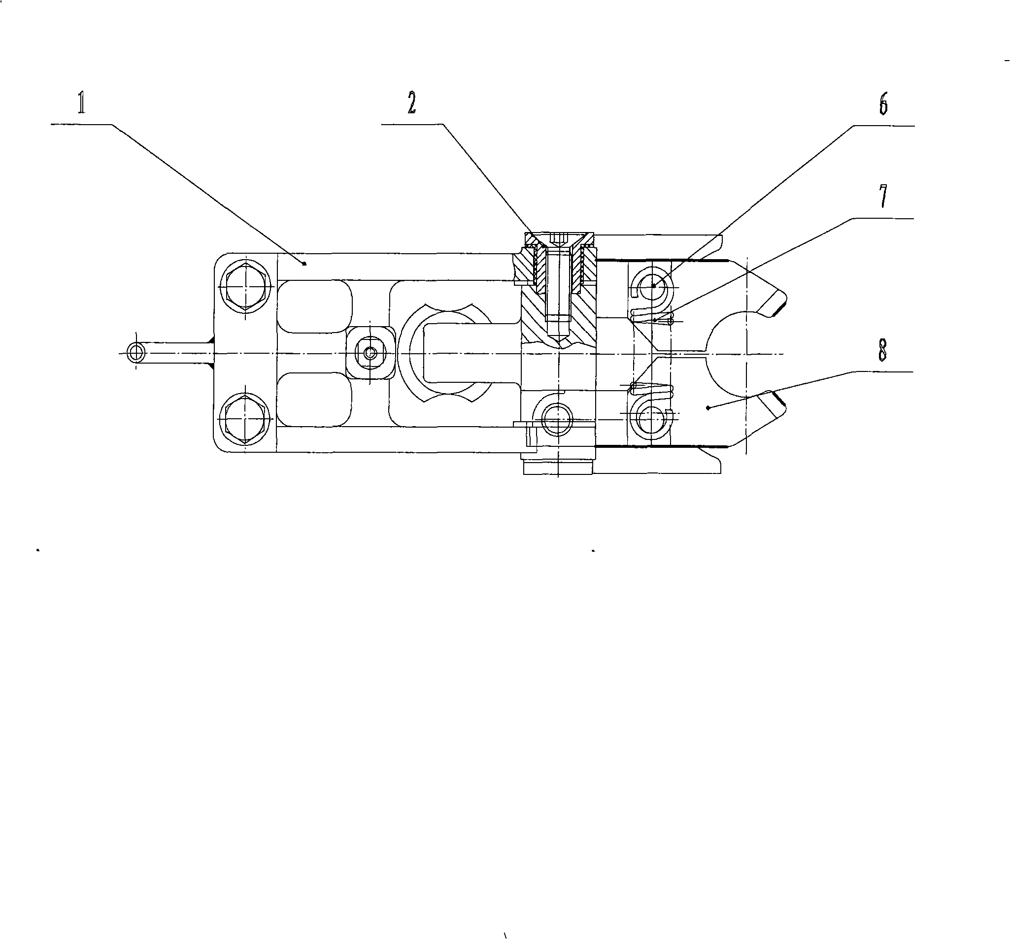
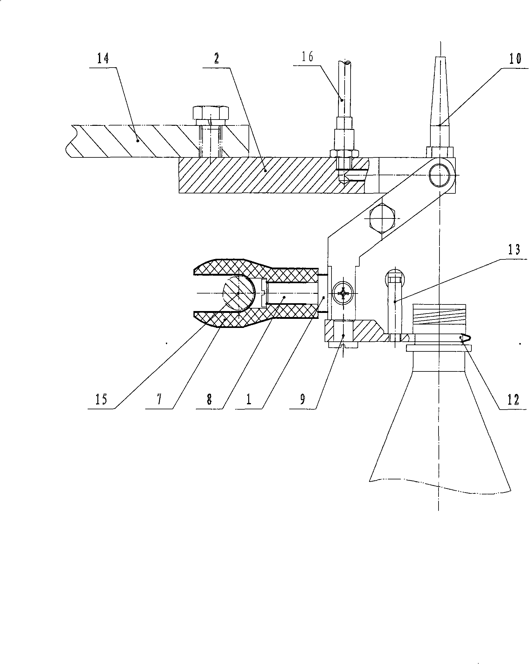
[0012] Such as figure 2 As shown, the bottle rinsing device of the present invention includes: the support block 2 is fixed on the rotary disk 14, and the left toggle lever 4 and the right toggle lever 5 are respectively installed on both sides of the support block 2 with a small shaft 11 and can be rotated around the small shaft 11 turn. There is distance body 6 to connect between two toggle levers. The left and right clips 12 are installed on the left toggle 4 and the right toggle 5 with screws 9 respectively, and column pins 13 are installed on the left and right clips 12 for fixing the extension spring 3 to control the closing of the left and right clips 12. The center of rotation of the left toggle lever 4 and the right toggle lever 5 is on the center line of the left and right clips 12 clamping bottles. The support body 1 is fixed on the side of the left toggle lever 4 and the right toggle lever 5. The retaining ring screw 8 connects the sliding fork 7 to the support ...


PUM


Abstract

The invention provides a bottle punching clamp. A supporting block is fixed on a rotary disc; a left elbow rod and a right elbow rod are respectively arranged at the two sides of the supporting block by a small shaft; the two elbow rods can rotate around the small shaft; the two elbow rods are connected with each other by a fixed distance body; a left clamping sheet and a right clamping sheet are provided with pins which are used for fixing a pullback spring; a supporting body is fixed on the side surfaces of the two elbow rods; a sliding fork is connected on the supporting body by a retaining ring screw; the sliding fork is contacted with a turnover guideway and can slide along the turnover guideway, thus driving the elbow rods and the clamping sheets to turn over. After the bottle clamped by the left clamping sheet and the right clamping sheet is turned over by 180 degrees, the distance from the center of the bottle to the center of the rotary disc is kept unchangeable, and the distance of two adjacent bottles before and after the turnover of the bottle is also kept unchangeable; therefore, the bottle punching clamp can be applicable to large bottles without the necessary to consider the mutual interference of the two adjacent bottles after the turnover of the bottle. The bottle punching clamp saves the installation space and saves the production cost compared with the original bottle punching clamp.

Description

technical field [0001] The invention relates to a bottle-clamping and rinsing device, in particular to a bottle-rinsing device for clamping and rinsing bottles in the beverage production process. Background technique [0002] In the beverage production process, in order to ensure the cleanliness of beverages, the bottles used for filling beverages must be cleaned before entering the filling process. When cleaning, the bottle clamps the bottle and turns it over so that the bottle mouth is downward, and then the bottle is rinsed by the nozzle. . Such as figure 1 and figure 2 As shown, a common bottle rinsing device has a structure comprising: a bracket 1 is installed on a rotary disk 11, an overturning frame 9 is fixed on the bracket 1 by a rotating shaft 2 and can rotate around the rotating shaft 2, and a bottle rinsing device is installed on the overturning frame 9 The nozzle 10 is connected to the liquid inlet pipe 13, and the rinse nozzle 10 is connected to the liquid ...

Claims


Application Information

Patent Timeline
IPC IPC(8): B08B13/00B08B9/28
Inventor 黄振华薛宇施华军
Owner JIANGSU ASG PACKAGING MACHINERY GRP
Why Eureka
Try Eureka