Memory control methods and circuit thereof

A technology of control circuit and control method, which is applied in the direction of static memory, digital memory information, information storage, etc., can solve problems such as impossibility to achieve optimal performance and fluctuation, and achieve the effect of optimal control performance

Active Publication Date: 2009-02-11
MEDIATEK INC
View PDF0 Cites 23 Cited by
  • Summary
  • Abstract
  • Description
  • Claims
  • Application Information

AI Technical Summary

Problems solved by technology

[0004] However, the phase of DQ signal and DQS signal will fluctuate due to noise or internal / external environmental reasons, such as temperature change
Therefore, it is not possible to achieve optimum performance for the memory module 10, and especially for the controller 14, using a fixed amount of delay.

Method used


Image

  • Memory control methods and circuit thereof
  • Memory control methods and circuit thereof
  • Memory control methods and circuit thereof

Examples


Embodiment Construction

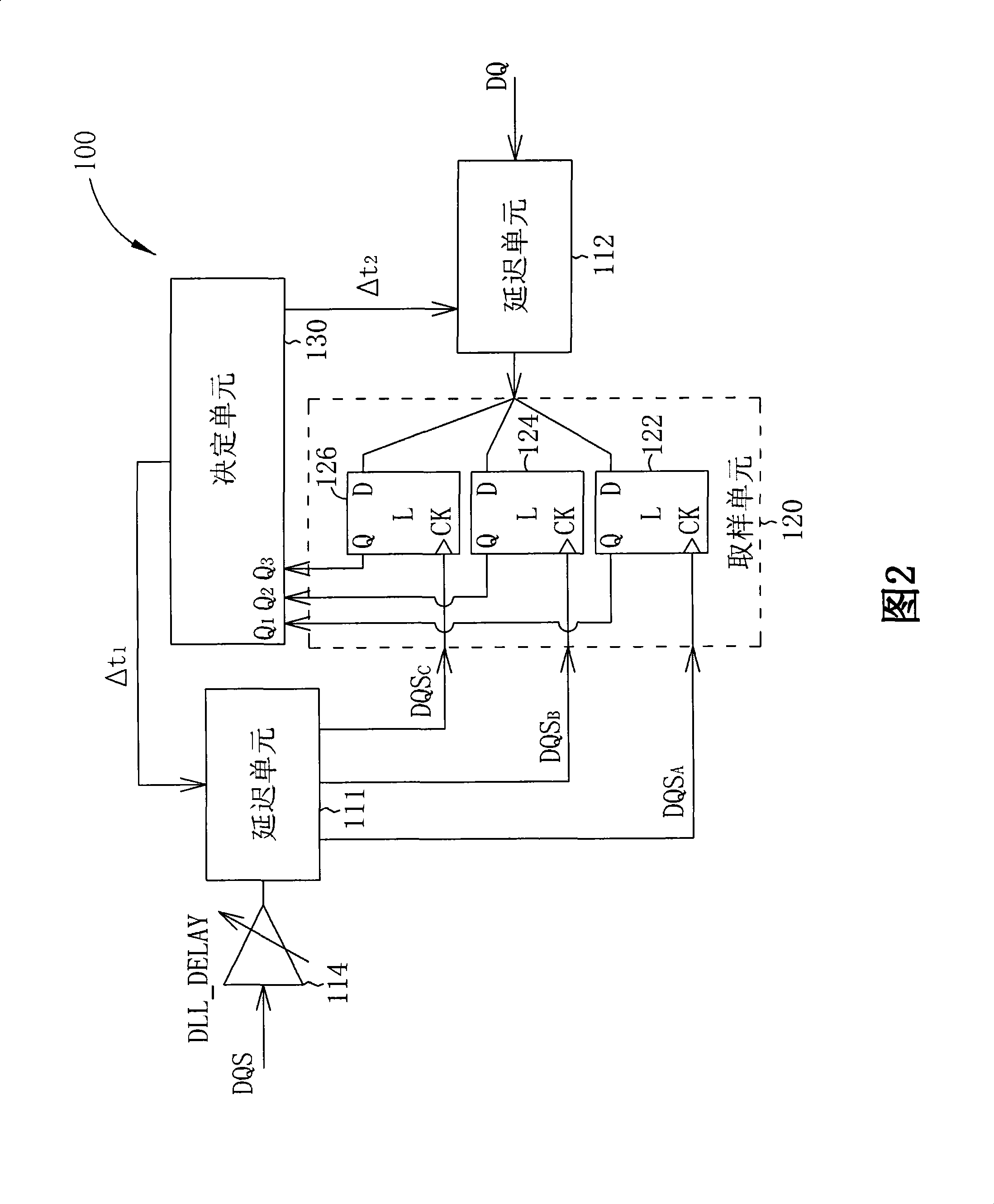
[0015] Please refer to FIG. 2 , which is a block diagram of a memory control circuit 100 according to a first embodiment of the present invention. In this embodiment, the memory control circuit 100 includes delay units 111 , 112 and 114 , a sampling unit 120 and a decision unit 130 . The memory control circuit 100 receives a data signal (such as a DQ signal) and a raw data strobe signal (such as a DQS signal) through the delay units 112 and 114 respectively. In addition, the delay unit 114 further includes a single delay cell (delay cell), as shown in FIG. 2 , the single delay cell has an adjustable delay value DLL_DELAY. The adjustable delay DLL_DELAY is set to a constant phase delay of 90 degrees. As shown in FIG. 2 , the sampling unit 120 includes latches 122 , 124 and 126 .

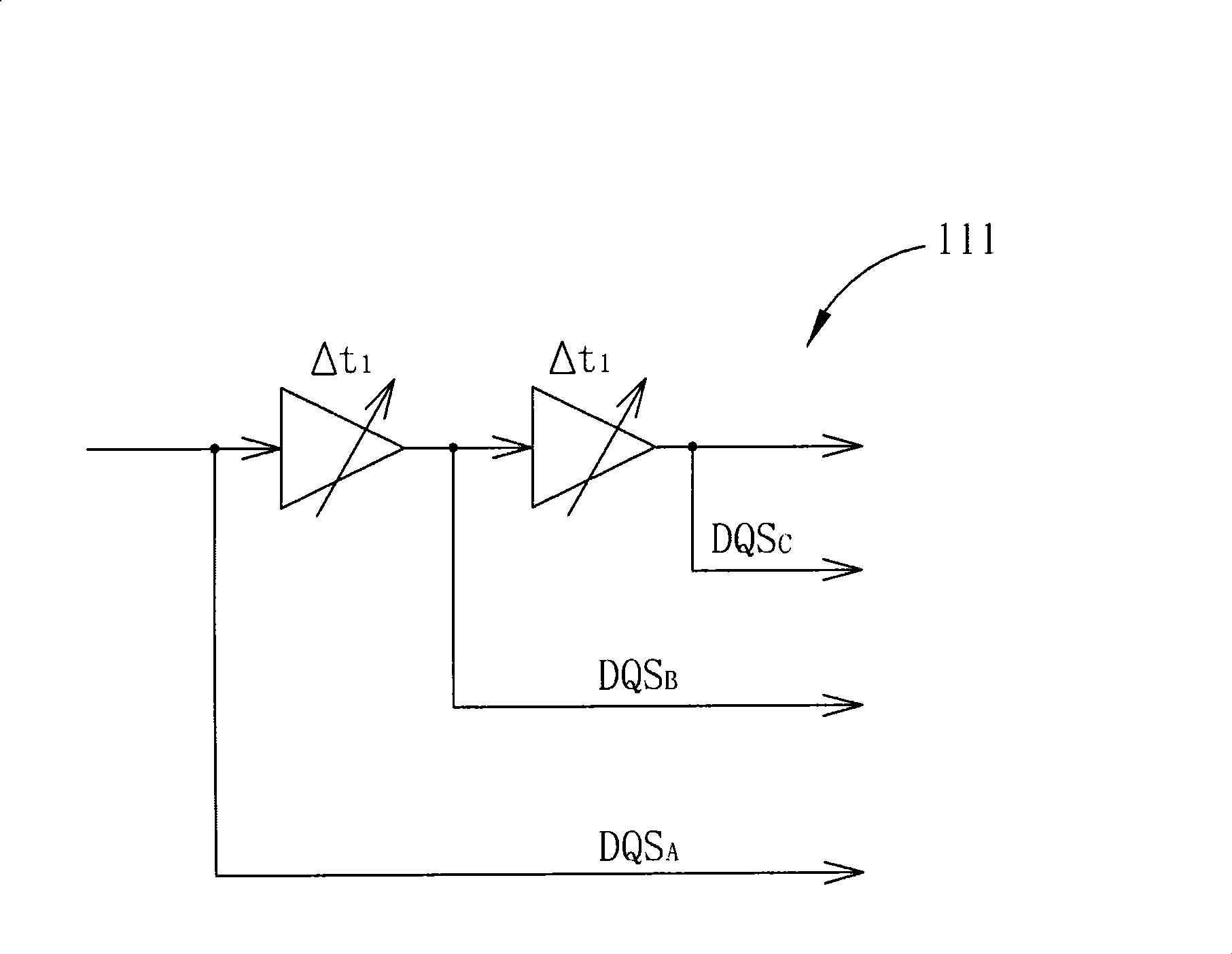
[0016] Please refer to Figure 2 and image 3 . image 3 is a schematic diagram of the delay unit 111 according to the first embodiment of the present invention. The delay unit 111 includes two de...


PUM


Abstract

A memory control method for adjusting sampling points utilized by a memory control circuit receiving a data signal and an original data strobe signal of a memory includes: utilizing at least one delay unit to provide a plurality of sampling points according to the original data strobe signal; sampling according to the data signal by utilizing the plurality of sampling points; and analyzing sampling results to dynamically determine a delay amount for delaying the original data strobe signal, whereby a sampling point corresponding to the delayed data strobe signal is kept centered at data carried by the data signal. Therefore, the invention can dynamically adjust the sampling points to achieve a best memory control effect.

Description

technical field [0001] The present invention relates to memory control, in particular to a memory control method capable of dynamically adjusting sampling points and related circuits. Background technique [0002] Please refer to figure 1 , figure 1 is a schematic diagram of a memory module 10 in the prior art. The memory module 10 includes a dynamic random access memory (dynamic random access memory) 12 and a controller 14, wherein the controller 14 uses a data signal and a data strobe signal (data strobe signal) to access the dynamic random access memory 12, and the data signal is as figure 1 Among DQ signals, data strobe signals such as figure 1 The concept and operation of the DQS signal, the DQ signal and the DQS signal are well known to those skilled in the art, so details are not repeated here. [0003] Generally speaking, to manufacture an electronic component including a memory module 10, a manufacturer needs to combine an independent DRAM 12 and a controller 14...

Claims


Application Information

Patent Timeline
Patent Type & Authority Applications(China)
IPC IPC(8): G11C7/10
CPCG11C7/1066G11C7/1051G11C7/1093G11C7/1078G11C2207/2254
Inventor 曾瑞兴
Owner MEDIATEK INC
Why Eureka
Try Eureka