Decoding of binaural audio signals

An audio signal, two-channel technology, applied in the field of decoding two-channel audio signals, can solve the problem of unoptimized generation of two-channel signals, and achieve the effect of simplifying computational complexity, improving efficiency, and reducing computational complexity

Inactive Publication Date: 2009-02-11
NOKIA CORP
View PDF0 Cites 30 Cited by
  • Summary
  • Abstract
  • Description
  • Claims
  • Application Information

AI Technical Summary

Problems solved by technology

It is clear that this method is also not optimized for generating binaural signals

Method used


Image

  • Decoding of binaural audio signals
  • Decoding of binaural audio signals
  • Decoding of binaural audio signals

Examples


Embodiment approach

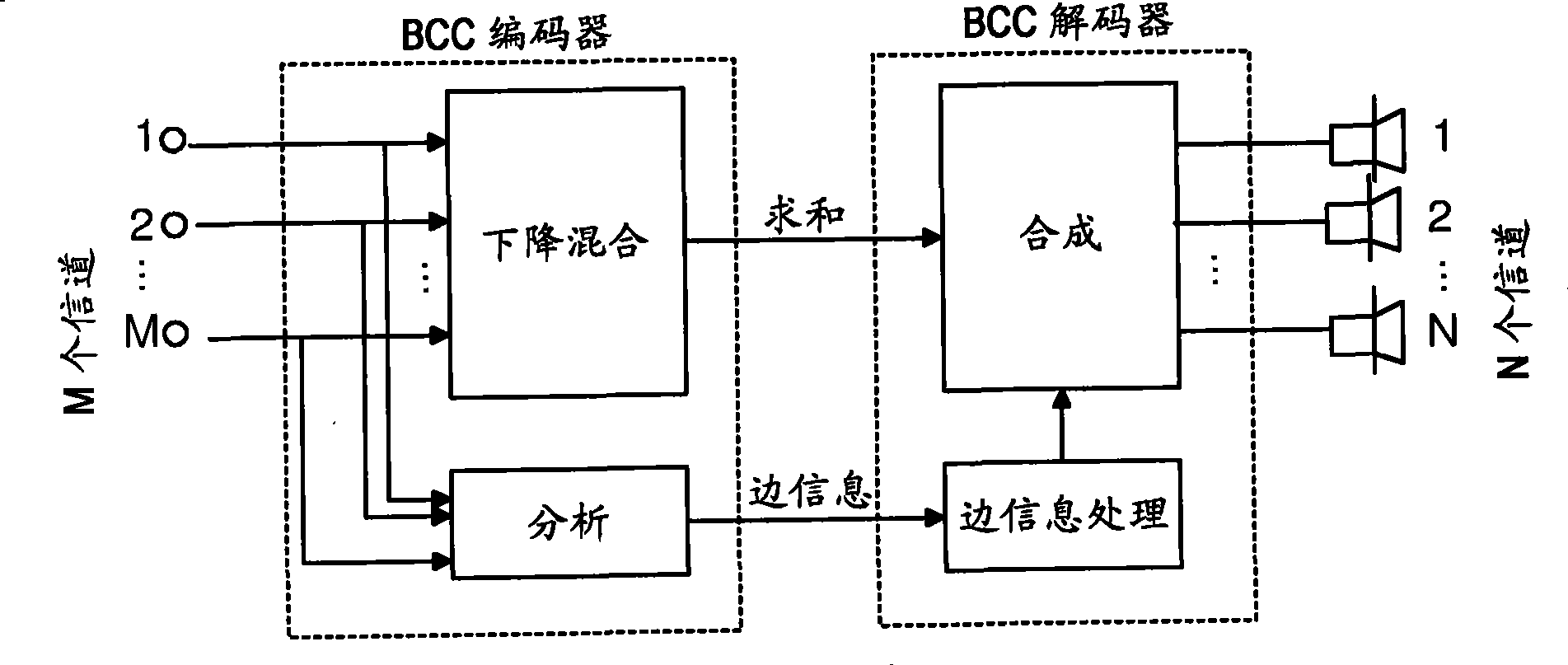
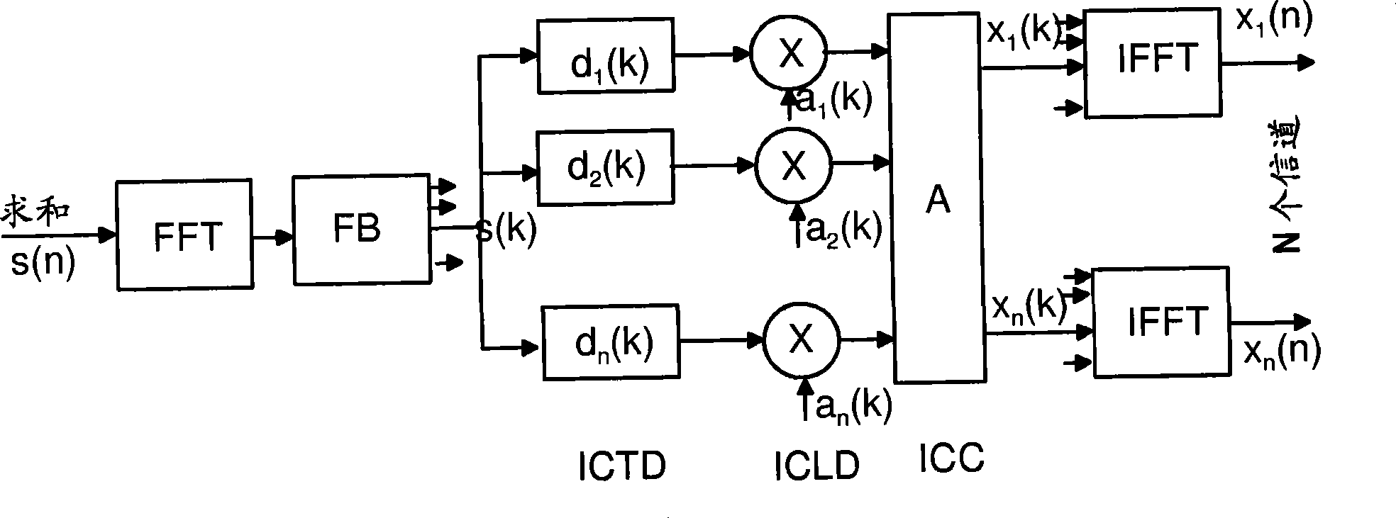
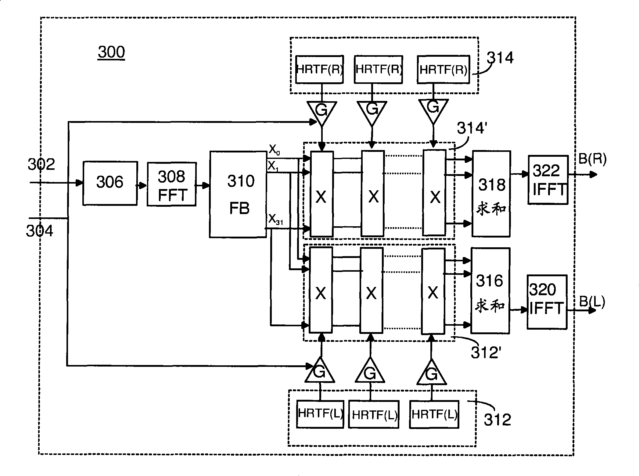
[0032] According to one embodiment, the side information does not necessarily include inter-channel clues (i.e. Inter-Channel Time Difference (ICTD), Inter-Channel Level Difference (ICLD), and Inter-Channel Coherence (ICC)) as in the BCC scheme, but only It is sufficient to include a set of gain estimates for defining the sound pressure distribution among the original mixed channels in each frequency band. In addition to the gain estimates, the side information preferably includes the number and position of loudspeakers in the original mix relative to the listening position, and the frame length utilized. According to one embodiment, instead of sending the gain estimate as part of the side information from the encoder, the gain estimate is calculated in the decoder from inter-channel cues of the BCC scheme, eg ICLD.

[0033] The decoder 300 further comprises a windowing unit 306, wherein the monophonized signal is first divided into time frames of the used frame length, and th...


PUM


Abstract

A method for synthesizing a binaural audio signal, the method comprising: inputting a parametrically encoded audio signal comprising at least one combined signal of a plurality of audio channels and one or more corresponding sets of side information describing a multi-channel sound image; and applying a predetermined set of head-related transfer function filters to the at least one combined signal in proportion determined by the corresponding set of side information to synthesize a binaural audio signal.

Description

[0001] related application [0002] This application claims priority to International Application PCT / FI2006 / 050014, filed January 9, 2006, US Application 11 / 334,041, filed January 17, 2006, and US Application 11 / 354,211, filed February 13, 2006. technical field [0003] The present invention relates to spatial audio coding, and more particularly to the decoding of binaural audio signals. Background technique [0004] In spatial audio coding, a two-channel / multi-channel audio signal is processed such that the audio signal is reproduced on different audio channels that are different from each other, thereby giving the listener the impression of a spatial effect surrounding the audio source. This spatial effect can be produced by recording the audio directly into a suitable format for multi-channel or binaural reproduction, or it can be simulated in any two-channel / multi-channel audio signal, which is called spatialization. [0005] It is generally known that, for headphones...

Claims


Application Information

Patent Timeline
Patent Type & Authority Applications(China)
IPC IPC(8): G10L19/00G10L19/02H04S5/00H04R5/00
CPCH04S2420/01H04S2400/01H04S3/004G10L19/008G10L19/0204H04S3/002G10L19/022G10L19/02H04S2420/03
Inventor P·奥雅拉J·蒂尔屈M·瓦阿纳南M·塔米
Owner NOKIA CORP
Why Eureka
Try Eureka