System and Method for Reducing Specular Reflection

a specular reflection and system technology, applied in the field of image capture and data collection systems, can solve the problems of specular reflection, glare, cost and time-consuming implementation, and achieve the effects of reducing specular reflection, reducing cost, and reducing specular reflection

Inactive Publication Date: 2008-04-03
NOVANTA CORP
View PDF13 Cites 19 Cited by
  • Summary
  • Abstract
  • Description
  • Claims
  • Application Information

AI Technical Summary

Benefits of technology

[0005]It is therefore a principal object and advantage of the present invention to provide a simple system and method for reducing specular reflection.
[0006]It is an additional object and advantage of the present invention to provide a less costly system and method for reducing specular reflection.
[0007]It is a further object and advantage of the present invention to provide a less intrusive system and method for reducing specular reflection
[0008]In accordance with the foregoing objects and advantages, the present invention comprises an optical imager that has been programmed to reduce specular reflection (i.e., glare) in a captured image to reduce the negative impact of the specular reflection on image interpretation. Specular reflection in reduced by reviewing the image to be decoded on a pixel-by-pixel basis and looking at the value of each pixel in the area of interest. If the amplitude of the pixel value is greater than a threshold, the pixel value is replaced with a predetermined value that may be fixed, computed via a calibration process, or dynamically determined from frame to frame. The predetermined value may be selected by using a weighted sum of pixels around the current pixel or another image processing technique to reduce noise in the area of interest. The image produced by this process will have no values greater than the threshold and may thus be more easily decoded by barcode decoding or image processing algorithms.

Problems solved by technology
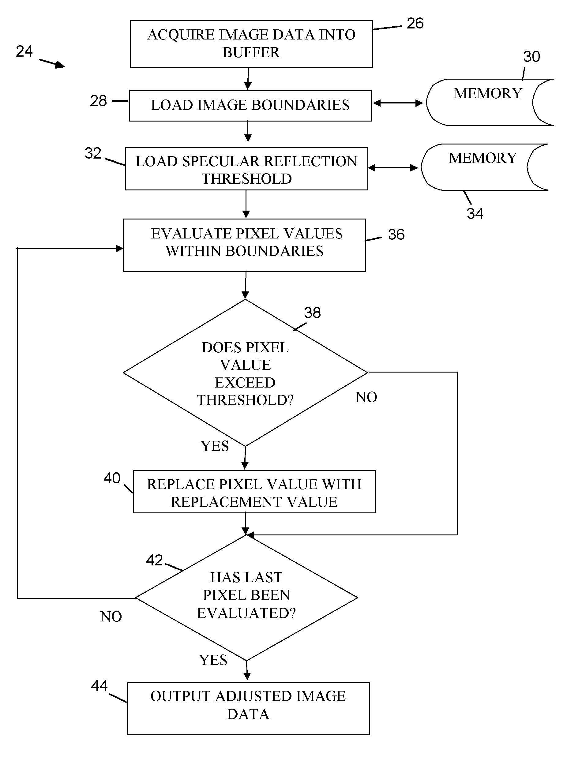
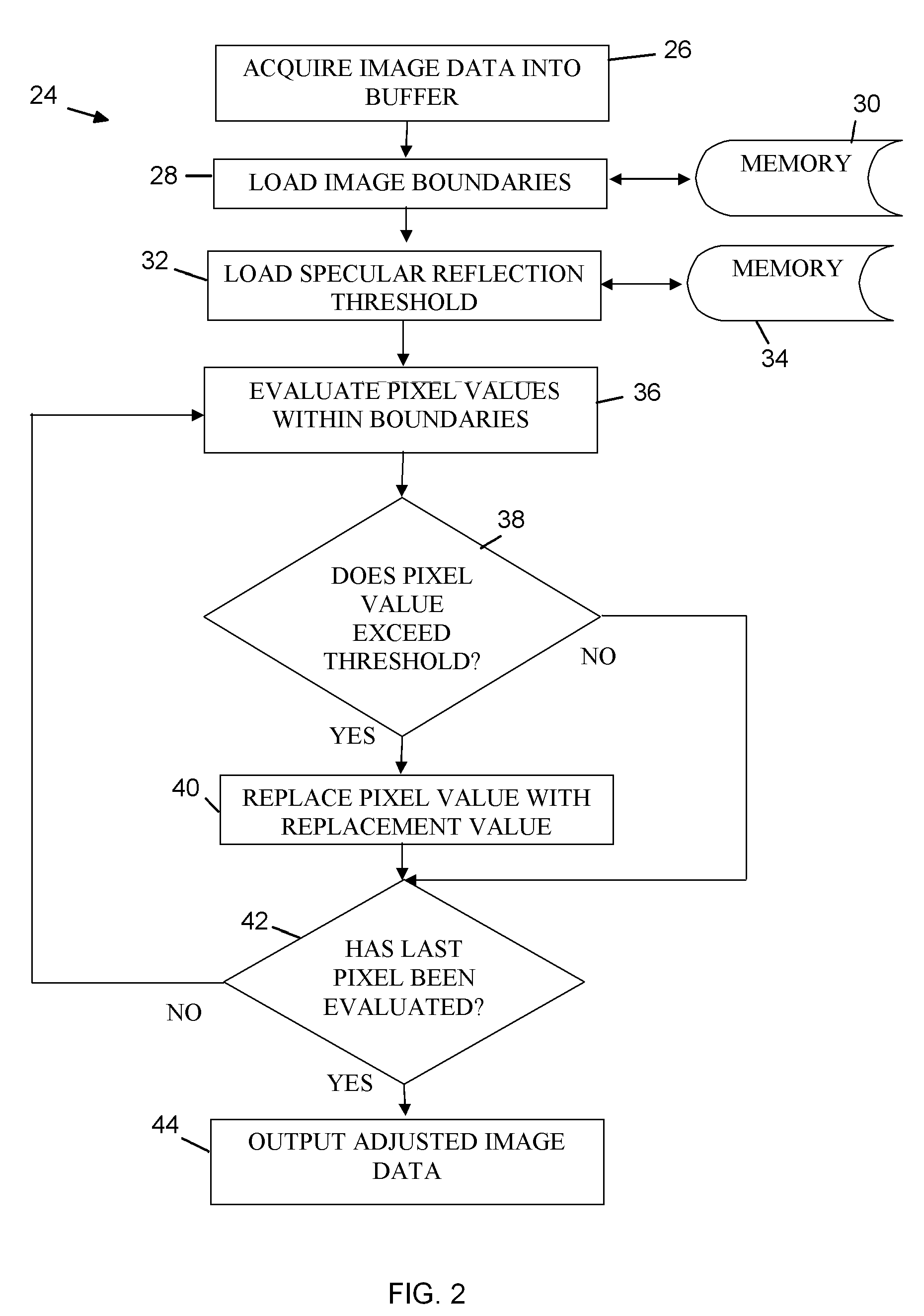
Specular reflection, or glare, often presents a problem during the interpretation of images captured by automatic identification systems, such as bar code scanners or vision processing devices.
These systems, however, require additional hardware and strategic positioning of the illumination source for proper functioning and are therefore costly and time consuming to implement.

Method used


Image

  • System and Method for Reducing Specular Reflection
  • System and Method for Reducing Specular Reflection
  • System and Method for Reducing Specular Reflection

Examples


Embodiment Construction

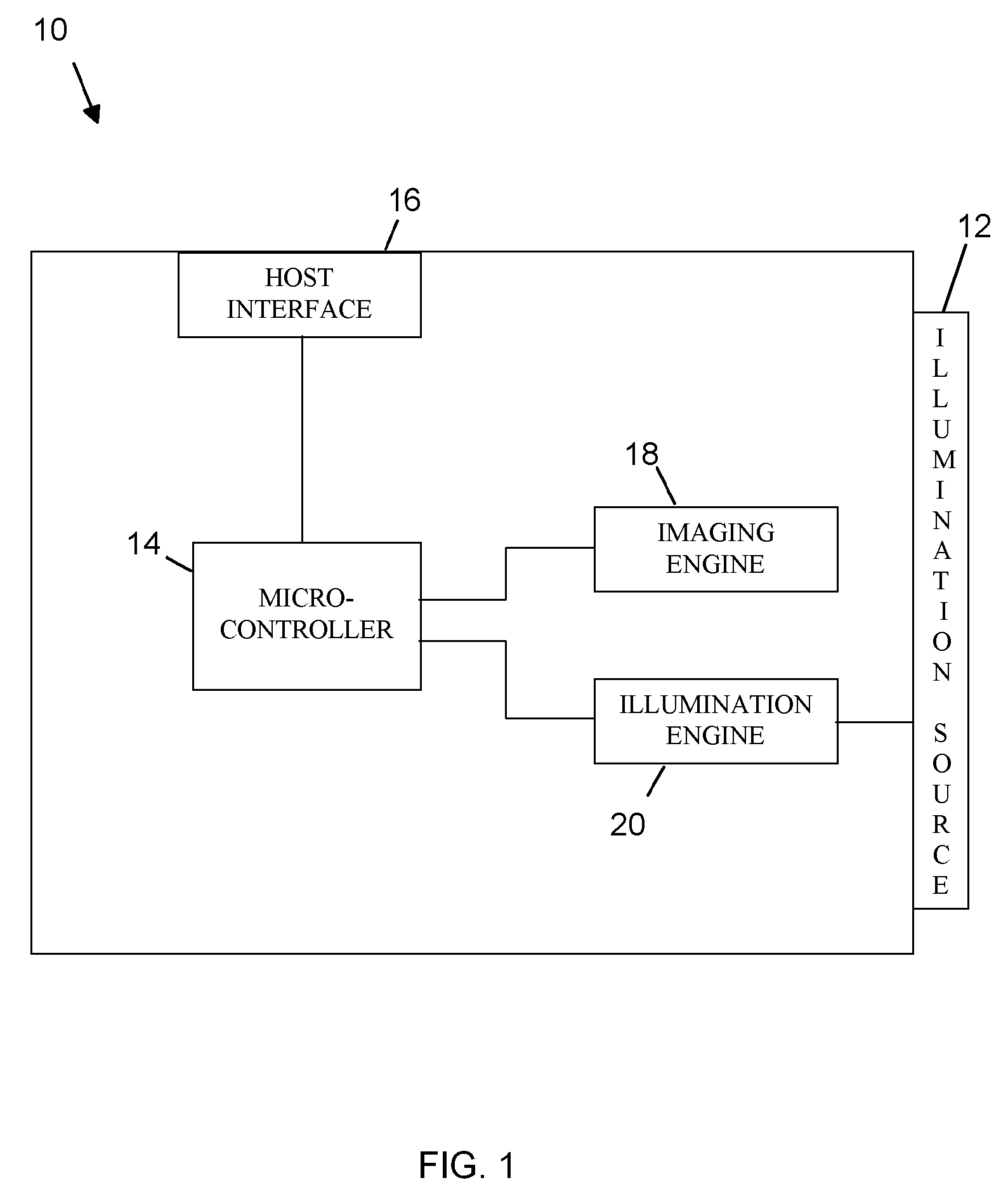
[0014]Referring now to the drawings, wherein like reference numerals refer to like parts throughout, there is seen in FIG. 1, an imaging unit 10 according to the present invention, Imaging unit 10 preferably includes an on-board illumination source 12 comprising one or more light emitting diodes (LEDs) of various wavelengths, to provide illumination of a target (not shown) to be imaged and interpreted. Alternatively, illumination source 12 may be separately attached to imaging unit 10 and positioned proximately thereto.

[0015]Imaging unit 10 further includes a microcontroller 14 for managing imaging and illumination operations, performing processing of captured images, and communicating with a remote device, such as a host computer, if desired. For example, imaging unit 10 may include a host interface 16, such as a conventional RS232 transceiver and associated 12 pin FFC jack. Alternatively, interface 16 may comprise other conventional buses, such as USB, IEEE, 1394, IrDA, PCMCIA, or...


PUM


Abstract

An imaging unit programmed to reduce specular reflection in a captured image and improve the interpretation of decodable information within the image. The imaging unit is programmed to scan a predetermined region within the image that is susceptible to specular reflection, evaluate the pixel values within the region against a threshold value that is representative of specular reflection, and then replace the pixel value found to represent specular reflection with replacement pixel values that do not corrupt interpretation of the decodable information in the predetermined region. The threshold value and replacement values may be determined on an ad hoc basis and stored in local memory, or calculated for each captured image.

Description

BACKGROUND OF THE INVENTION [0001]1. Field of the Invention[0002]The present invention relates to image capture and data collection systems and, more specifically, to a system and method for reducing specular reflection in optical images to be interpreted and decoded.[0003]2. Description of the Related Art[0004]Specular reflection, or glare, often presents a problem during the interpretation of images captured by automatic identification systems, such as bar code scanners or vision processing devices. Conventional methods of reducing specular reflection involve sophisticated systems having multiple light sources and / or imagers. For example, some systems use an array of mirrors for selecting specific wavelengths of light and a detector having two charged coupled devices (CCDs) tuned to different wavelengths to take two images of a target. The detector is programmed to selectively buffer the image data and correct for any specular reflection using information obtained from both CCDs. ...

Claims


Application Information

Patent Timeline
Patent Type & Authority Applications(United States)
IPC IPC(8): G06K9/40G06V10/28G06V10/30
CPCG06K9/40G06K9/38G06V10/28G06V10/30
Inventor FORD, BRIAN PAUL
Owner NOVANTA CORP
Why Eureka
Try Eureka