Surface-treated cooled wire

A surface treatment and wire technology, applied in the field of new cooling wires, can solve the problems of increased loss, waste of raw materials for wires, and increased difficulty of wire construction, etc., and achieve the effects of reduced energy loss, strong self-cleaning function, and excellent heavy-duty anti-corrosion performance

Inactive Publication Date: 2015-08-12
JIANGSU ZHONGTIAN TECH CO LTD
View PDF5 Cites 3 Cited by
  • Summary
  • Abstract
  • Description
  • Claims
  • Application Information

AI Technical Summary

Problems solved by technology

The conventional method to increase the transmission capacity of the wire is to increase the current-carrying area of ​​the wire or to increase the operating temperature of the wire. Increasing the current-carrying area of ​​the wire not only wastes raw materials, but also increases the difficulty of construction of the wire; although increasing the operating temperature of the wire can Increase the transmission capacity of the wire, but at the same time increase the loss in the transmission process of the line, which does not meet the construction requirements of "two types and three new" transmission lines

Method used


Image

  • Surface-treated cooled wire
  • Surface-treated cooled wire
  • Surface-treated cooled wire

Examples


Embodiment 1

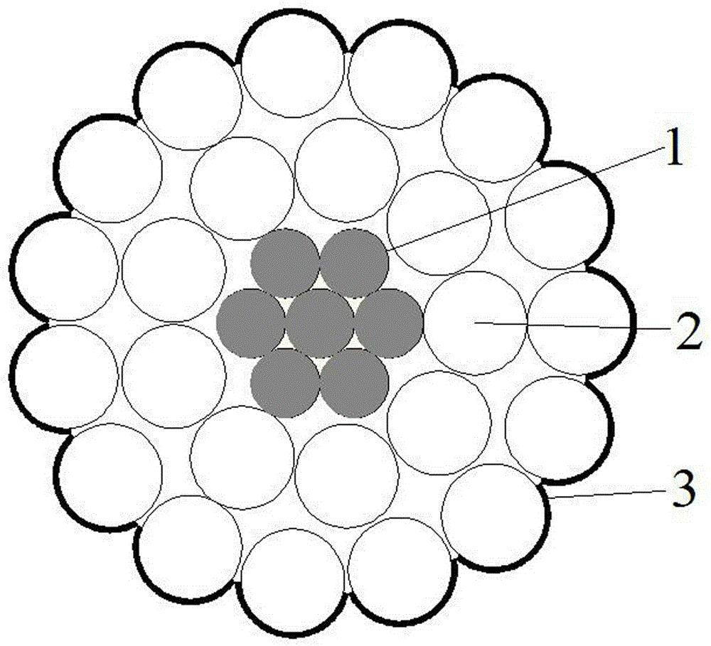
[0039] Embodiment 1: see figure 1 , invented a surface-treated cooling wire, including a central strengthening core aluminum-magnesium-silicon alloy stranded wire 1, a circular aluminum conductor 2, and a fluorocarbon coating 3 containing fluorocarbon elements coated on the outermost layer. The fluorocarbon coating is commercially available fluorocarbon coating.

Embodiment 2

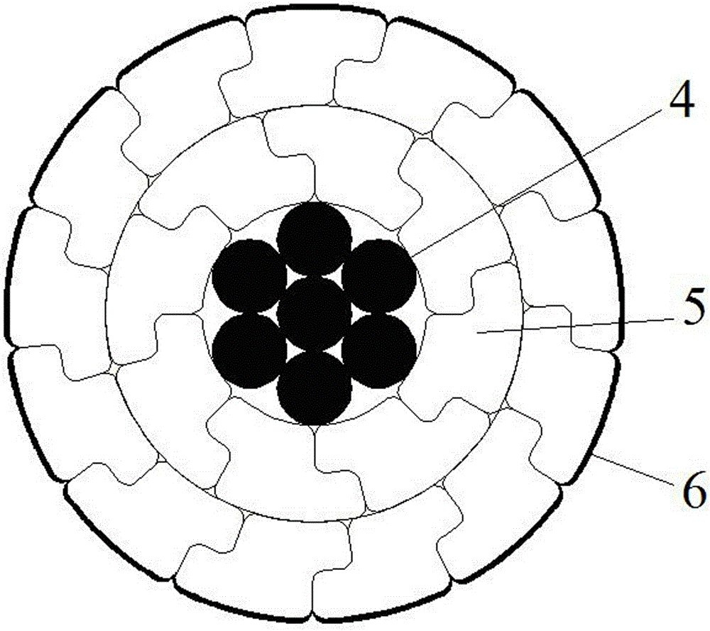
[0040] Example 2: see figure 2 , invented a surface-treated cooling wire, including a central reinforced core steel strand 4, a ZS-shaped aluminum conductor 5, a fluorocarbon coating 6 that contains fluorocarbon elements on the outermost layer, and a fluorocarbon element that is coated on the outermost layer Low absorption color, light brown, yellow, white, pink, light green, light yellow, brown, black, off-white, dark gray and other colors of fluorocarbon coating 6.

Embodiment 3

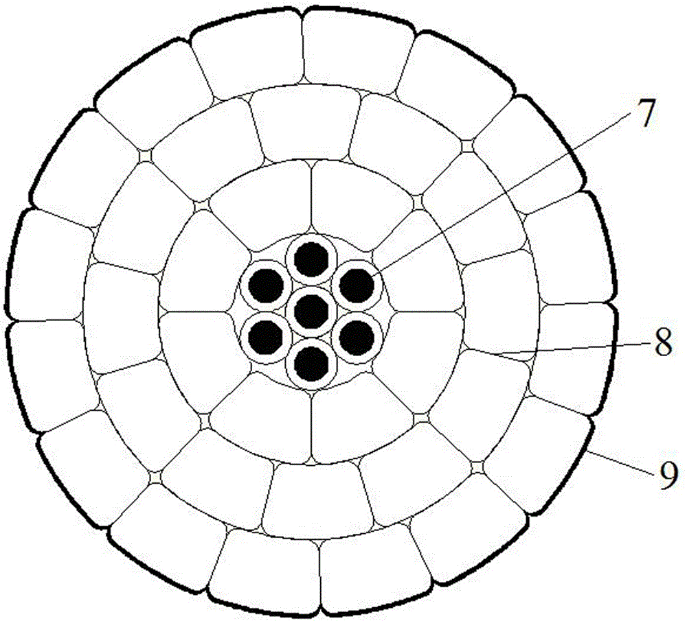
[0041] Embodiment 3: see image 3 , invented a surface-treated cooling wire, including a central reinforcement core aluminum-clad steel strand 7, a T-shaped aluminum conductor 8, a fluorocarbon coating 9 coated with fluorocarbon elements on the outermost layer, and a fluorine-containing carbon element coated on the outermost layer Carbon element low absorption color, light brown, yellow, white, pink, light green, light yellow, brown, black, off-white, dark gray and other colors of fluorocarbon coating9.

[0042] The surface-treated cooling wire of the present invention forms a permanent layer of high-radiation and low-endothermic paint on the surface by spraying the outermost layer of the wire with high-radiation and low-endothermic paint, so that this new type of surface-treated cooling wire is comparable to the same specification Compared with wires, under the same current carrying capacity, the surface temperature of wires can be reduced by 5°C to 20°C. It reduces energy l...


PUM


Abstract

The inventions relates to a surface-treated cooled wire and to the field of overhead conductors, and specifically to a novel cooled wire with a surface coated with high-radiation lowly-endothermic coating. The surface-treated cooled wire comprises central reinforcing cores, conductors, and an outermost coating. The conductors are stranded on the outer side of the central reinforcing cores and are coated with the outermost coating. The outermost coating is a high-radiation lowly-endothermic coating layer and is a fluorocarbon coating containing fluorocarbon element. The surface-treated cooled wire is easy to manufacture, low in cost increase, decreased in used temperature, and resistant to weather and corrosion. The outermost coating forms a permanent layer with high-radiation lowly-endothermic coating on the surface of the surface-treated cooled wire. Compared with a wire with same specification, the novel surface-treated cooled wire is decreased in surface temperature by 5 to 20 degrees centigrade in the case of same current-carrying capacity. As a result, line energy loss in a transmission process is reduced and low-carbon economy is achieved.

Description

technical field [0001] The surface-treated cooling wire of the present invention relates to the field of overhead wires, in particular to a new type of cooling wire whose surface is sprayed with a coating with high radiation and low heat absorption. Background technique [0002] In the construction of green power grid, through the implementation of "two types and three new" (resource-saving, environment-friendly, and new materials, new technologies, and new processes) transmission line construction, the area of ​​cultivated land occupied by power transmission and transformation projects is reduced, and the impact of the project on the environment is reduced. Save material loss in power transmission and transformation projects, and improve the capacity and technical level of power transmission and transformation projects. The conventional method to increase the transmission capacity of the wire is to increase the current-carrying area of ​​the wire or to increase the operatin...

Claims


Application Information

Patent Timeline
Patent Type & Authority Applications(China)
IPC IPC(8): H01B5/10H01B5/00
Inventor 吴明埝缪姚军尤伟任冯爱军
Owner JIANGSU ZHONGTIAN TECH CO LTD
Why Eureka
Try Eureka