Induction heating device

A technology for induction heating devices and heated objects, which is applied in the direction of induction heating devices, induction heating, electric heating devices, etc., and can solve the problems of sensor 5 thermal responsiveness and temperature detection accuracy degradation, and inability to heat heated objects 2, etc.

Active Publication Date: 2009-03-04
PANASONIC CORP
View PDF1 Cites 8 Cited by
  • Summary
  • Abstract
  • Description
  • Claims
  • Application Information

AI Technical Summary

Problems solved by technology

[0003] In the conventional induction heating device 5001, when the object to be heated 2 is not located directly above at least one of the sensors 5, the thermal responsiveness and temperature detection accuracy of the sensor 5 are deteriorated compared to when the object to be heated 2 is located directly above the sensor 5 , therefore, sometimes the induction heating device 5001 cannot accurately heat the heated object 2 at the set temperature.

Method used


Image

  • Induction heating device
  • Induction heating device
  • Induction heating device

Examples


Embodiment Construction

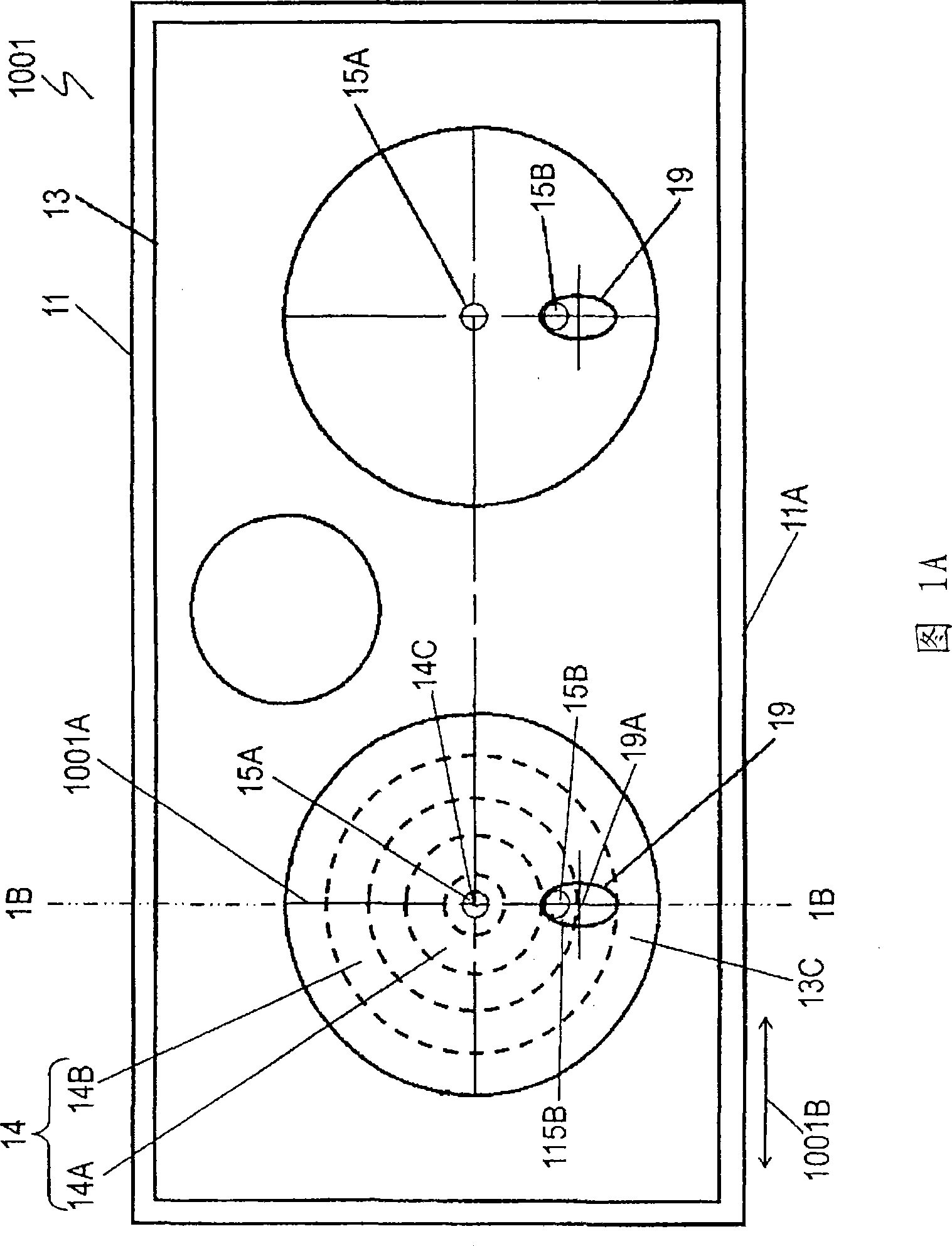
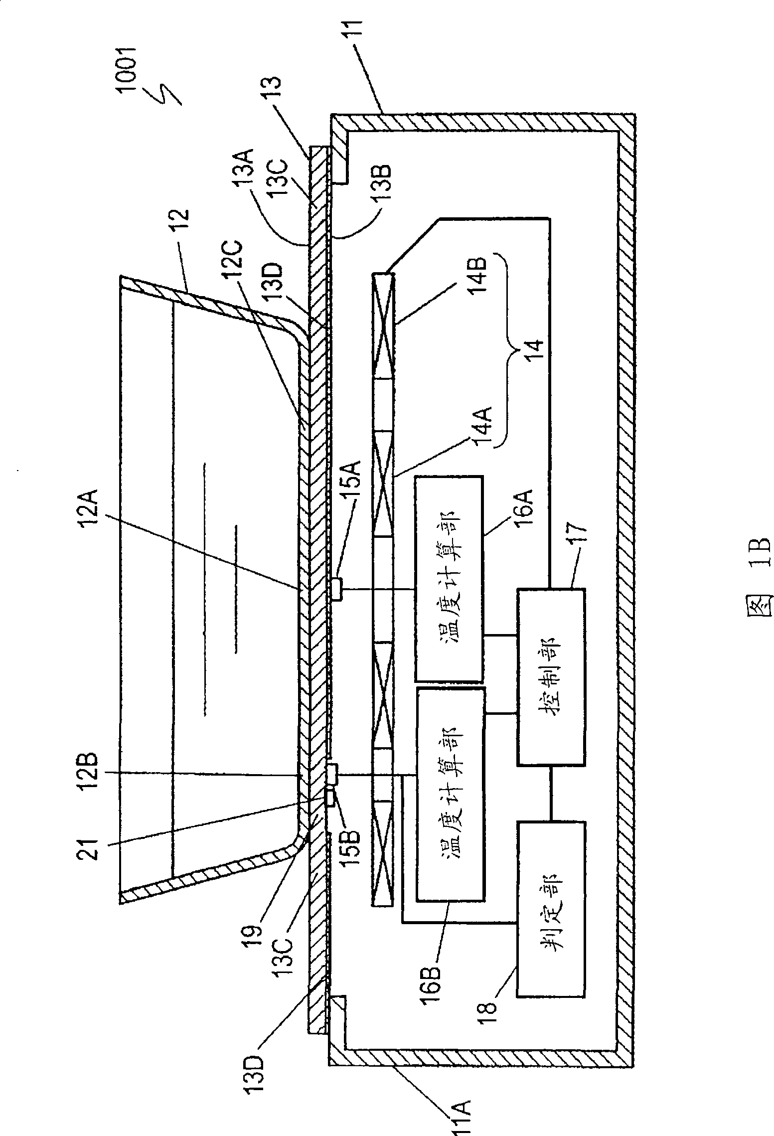
[0025] FIG. 1A is a top view of an induction heating device 1001 according to an embodiment of the present invention. FIG. 1B is a cross-sectional view of the induction heating device 1001 shown in FIG. 1A along line 1B-1B.

[0026] On the upper surface of the casing 11 is arranged a top plate 13 configured to place a heated object 12 such as a pan, and has an upper surface 13A and a lower surface 13B opposite thereto. A heating coil 14 for inductively heating the object 12 to be heated is disposed below the top plate 13 . The heating coil 14 is divided into an inner coil 14A and an outer coil 14B surrounding the inner coil 14A. The inner coil 14A and the outer coil 14B are electrically connected to each other. The entire bottom surface 12C of the object to be heated 12 can be uniformly heated by the inner coil 14A and the outer coil 14B. Contact heat-sensitive elements such as thermistors, that is, sensors 15A and 15B are arranged on the lower surface 13B of the top plate ...


PUM


Abstract

An induction heating device has a top plate on which an object to be heated is placed, a heating coil placed under the top plate and heating the object, a sensor placed under the top plate and detecting the temperature of the object, a determination section for determining whether the object is positioned right over the sensor, a control section for causing the heating coil to heat the object according to the temperature detected by the sensor, and a position display section provided at the top plate and indicating the position of the sensor. The position display section includes a sensing area where the sensor detects temperatures and has a greater area than the sensing area. With the induction heating device, an object to be heated can be reliably placed right over the sensor to enable accurate detection of the temperature of the object, so that the object can be accurately heated with a predetermined temperature.

Description

technical field [0001] The invention relates to an induction heating device. Background technique [0002] FIG. 2 is a cross-sectional view of a conventional induction heating device 5001 . On the upper surface of the casing 1, a top plate 3 on which an object to be heated 2 such as a pan is placed is provided. A heating coil 4 for inductively heating the object 2 to be heated is provided on the lower portion of the top plate 3 . The heating coil 4 is divided into an inner coil 4A and an outer coil 4B electrically connected to each other. Heat-sensitive elements such as thermistors, that is, sensors 5 are arranged respectively at the center of the heating coil 4 , that is, the inner coil 4A, between the inner coil 4A and the outer coil 4B, and on the back of the top plate 3 . The sensor 5 is provided below the object to be heated 2 , and the sensor 5 outputs a signal corresponding to the temperature of the object to be heated 2 . The temperature calculation unit 6 calcul...

Claims


Application Information

Patent Timeline
Patent Type & Authority Applications(China)
IPC IPC(8): H05B6/12
CPCH05B6/062H05B2213/05H05B2213/07H05B2213/04
Inventor 日下贵晶相原胜行庆岛敏弘
Owner PANASONIC CORP
Why Eureka
Try Eureka