Elevator
An elevator and electric current technology, applied in the field of elevators, can solve problems such as unusable and ineffective use of elevator energy
- Summary
- Abstract
- Description
- Claims
- Application Information
AI Technical Summary
Problems solved by technology
Method used
Image
Examples
Embodiment approach 1
[0030] First, Embodiment 1 of the present invention will be described.
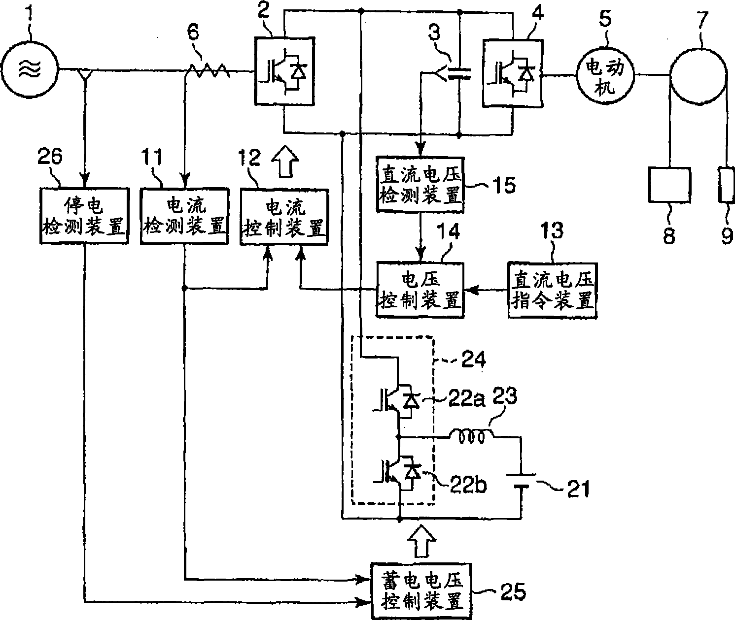
[0031] figure 1 The outline of the structure of the elevator in Embodiment 1 of this invention is shown.
[0032] exist figure 1 In the shown elevator, as a drive system, it is equipped with: a user power supply 1 as an external AC power supply, a converter device 2 for converting the AC voltage of the user power supply 1 into a DC voltage, and a device for smoothing the ripple of the DC voltage, that is, the pulsation. A smoothing capacitor 3, an inverter device 4 that converts the DC voltage into an AC voltage with a variable voltage and a variable frequency, and a motor 5 that operates by receiving electric power from the inverter device 4 . Furthermore, a current detector 6 is provided between the user power supply 1 and the inverter device 2 .
[0033] User power supply 1 is a three-phase power supply. The AC voltage generated by the three-phase power supply is full-wave rectified by the conver...
Embodiment approach 2
[0052] Next, Embodiment 2 of the present invention will be described. In addition, in the configuration of the elevator of the present embodiment, for those with figure 1 The parts that are the same as those shown will be omitted from description.
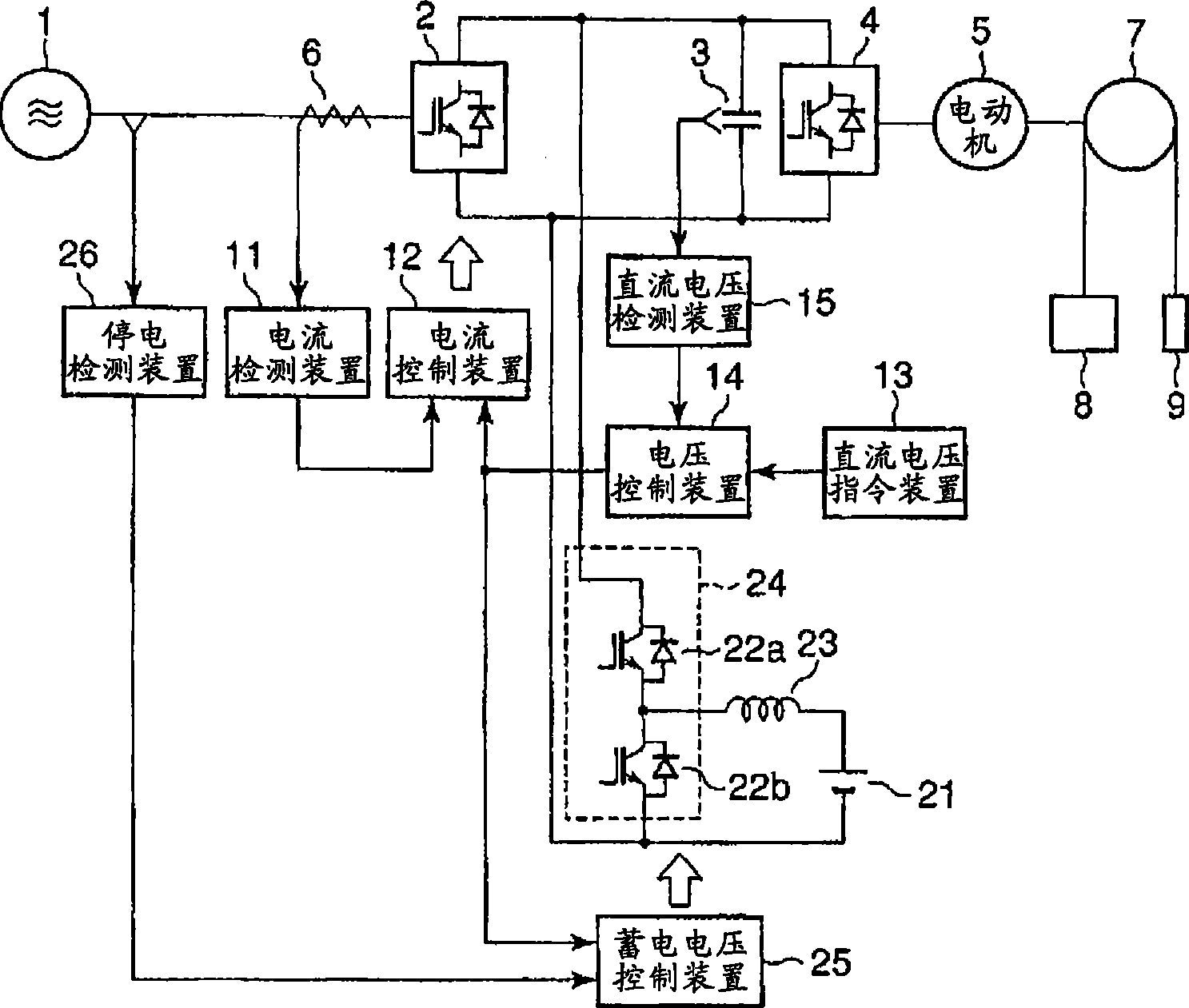
[0053] image 3 A schematic configuration of an elevator according to Embodiment 2 of the present invention is shown.
[0054] The electric storage voltage control device 25 of the elevator according to the second embodiment of the present invention is different from the first embodiment in that it is judged whether it is power running or not based on the direction of the current commanded from the voltage control device 14 when there is no power failure. is still in the regenerative operation, and the charging and discharging of the power storage device 21 is controlled according to the judgment result.
[0055] Next, the operation of the storage voltage control device 25 will be described. Figure 4 The type of operation of ...
Embodiment approach 3
[0060] Next, Embodiment 3 of the present invention will be described. In addition, in the configuration of the elevator of the present embodiment, for those with figure 1 The parts that are the same as those shown will be omitted from description.
[0061] Fig. 5 shows a schematic configuration of an elevator according to Embodiment 3 of the present invention.
[0062] As shown in FIG. 5 , the elevator according to Embodiment 3 of the present invention is different from Embodiment 1 in that a motor current detector 41 is provided between the inverter device 4 and the motor 5 .
[0063] In addition, the elevator of this embodiment is equipped with a motor current control device 42 as a motor current control mechanism, a motor current detection device 43, a speed detection device 44, a speed control device 45 as a speed control mechanism, and a speed command device as a speed command mechanism. 46.
[0064] The motor current detection device 43 detects the current value and ...
PUM
 Abstract
Description
Claims
Application Information
 - R&D
- Intellectual Property
- Life Sciences
- Materials
- Tech Scout
- Unparalleled Data Quality
- Higher Quality Content
- 60% Fewer Hallucinations
Browse by: Latest US Patents, China's latest patents, Technical Efficacy Thesaurus, Application Domain, Technology Topic, Popular Technical Reports.
© 2025 PatSnap. All rights reserved.Legal|Privacy policy|Modern Slavery Act Transparency Statement|Sitemap|About US| Contact US: help@patsnap.com


