Near field time domain beam forming method suitable for wideband signal

A broadband signal, near-field beam technology, applied in space transmit diversity, diversity/multi-antenna systems, and error prevention/detection through diversity reception, which can solve problems such as complex design and performance impact of near-field beamformers

Inactive Publication Date: 2009-03-11
NORTHWESTERN POLYTECHNICAL UNIV
View PDF0 Cites 14 Cited by
  • Summary
  • Abstract
  • Description
  • Claims
  • Application Information

AI Technical Summary

Problems solved by technology

But if the time delay in the near-field compensation term cannot be realized with high accuracy, then the performance of the near-field beamformer will be greatly affected
The near-field beamforming method based on radius conversion proposed by Kennedy, Abhayapala et al. can obtain accurate desired near-field characteristics in all directions (Abhayapala T D, Kennedy R A. Nearfield Broadband Array Design Using a Radially Invariant Modal Expansion. J Acoust Soc Amer , 2000, 107(1): 392~403), but this method is very complicated to design because it involves the harmonic solution of the wave equation

Method used


Image

  • Near field time domain beam forming method suitable for wideband signal
  • Near field time domain beam forming method suitable for wideband signal
  • Near field time domain beam forming method suitable for wideband signal

Examples


Embodiment Construction

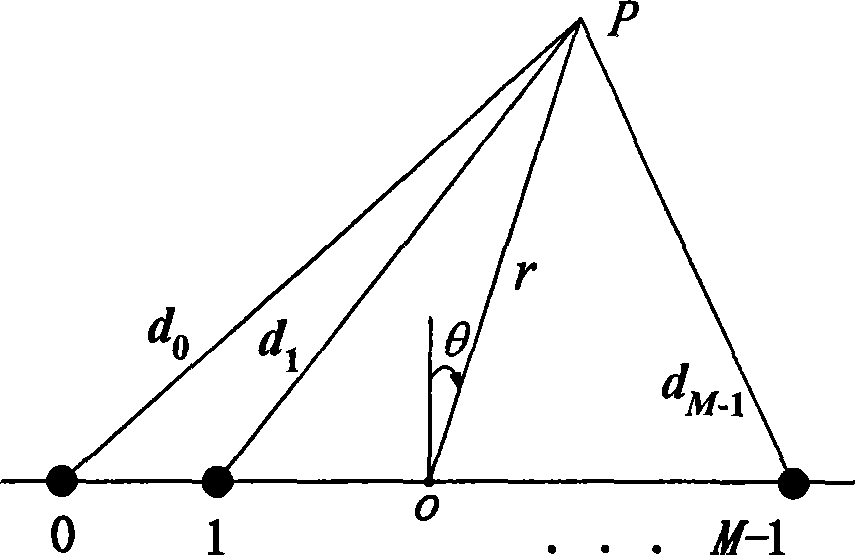
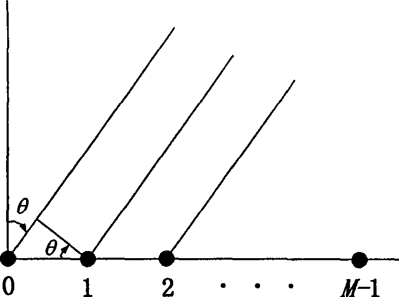
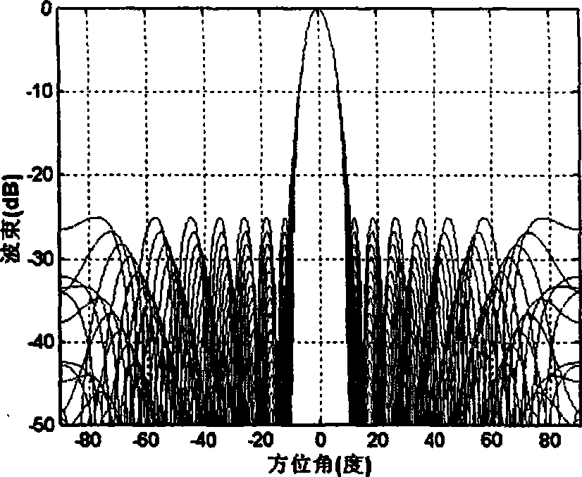
[0067] The example parameters are set as follows: a 30-element uniformly spaced linear array is used, the designed signal frequency band range is 2kHz to 4kHz, each array element is isotropic, and the array element spacing is half of the wavelength corresponding to the 4kHz frequency, that is, 0.1875 meters. The distance from the point sound source to the center of the array is r=20 meters, and the constant beam width is designed to point to the 0° direction, and the side lobes are required to be lower than -25dB.

[0068] The specific implementation process of this example is as follows:

[0069] 1) According to the requirements of the beam pattern, the far-field broadband beam weight coefficients are designed using the existing far-field technology under the assumption of the far-field And determine the time-domain realization structure of the far-field broadband beamformer.

[0070] The beams on 41 frequency points spaced at 50Hz in the working frequency band are as follo...


PUM


Abstract

The invention discloses a near field time domain beam forming method suitable for a wideband signal. According to the index requirements of a desired beam pattern, under the far field assumed condition, the existing far field beam forming technology is utilized to design and obtain the far field beam weight coefficient wm', and the time domain implementation structure is determined; according to the distance r of a near field signal source to a basic matrix center, the far field beam weight coefficient wm' is modified for obtaining the near field beam weight wm; the accurate time delay quantity needed by the modified weight coefficient in the near field beam forming is determined; the window minimum mean square error is adopted to design a finite impulse response fractional delay filter bank, so as to realize the accurate time delay needed in the near field beam forming; the fractional delay filter bank designed at the step (d) is added into a time domain beam former determined at the step (a), so the implementation structure of the near field time domain beam former is obtained. The invention is simple and effective, and is suitable for real time coefficient renovation and the wideband signal, thereby the complexity and the feasibility of the design can be improved greatly.

Description

technical field [0001] The invention relates to the beam forming technology in the field of array signal processing, in particular to the beam forming technology under near-field conditions and its time-domain implementation method. Background technique [0002] Beamforming is an important technique widely used in radar, sonar, ultrasound imaging and wireless communication. The present invention considers the beamforming process at the receiving end. In practical systems, multiple sensor array elements are often used to form a matrix according to certain geometric rules. The so-called beamforming is to process the output of each element of the basic array through certain processing, so that the total output of the array reaches the maximum in a certain direction, and the other directions become smaller accordingly. A beamformer can be regarded as a spatial filter, which can filter out signals at certain orientations in space and only allow signals at specified orientations...

Claims


Application Information

Patent Timeline
Patent Type & Authority Applications(China)
IPC IPC(8): H04B7/06H04L1/06
Inventor 孙超郭祺丽杨益新
Owner NORTHWESTERN POLYTECHNICAL UNIV
Why Eureka
Try Eureka