
Filler neck

A technology of filling pipes and oil guns, which is applied in the layout, power plant, transportation and packaging combined with the fuel supply of internal combustion engines, can solve the problems of complex structure and high air tightness, and achieve the effect of simple structure

Active Publication Date: 2009-04-01
TOYODA GOSEI CO LTD
View PDF1 Cites 8 Cited by
  • Summary
  • Abstract
  • Description
  • Claims
  • Application Information

AI Technical Summary

Problems solved by technology

However, the breather part requires high airtightness in order to prevent fuel vapor from leaking from between the filler pipe and the guide part, and there is a problem that the structure is complicated.

Method used


Image

  • Filler neck
  • Filler neck
  • Filler neck

Examples


Embodiment Construction

[0027] Next, one embodiment of the present invention will be described based on examples.

[0028] (1) Outline structure of oil supply device

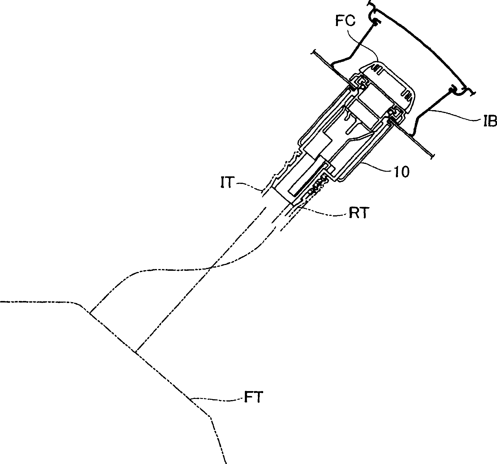
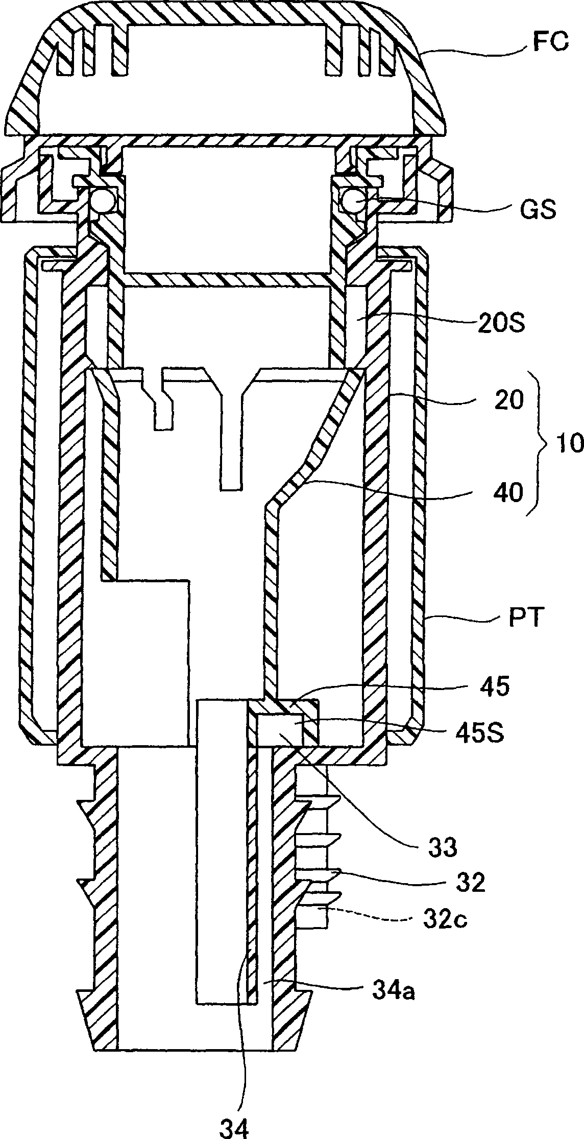
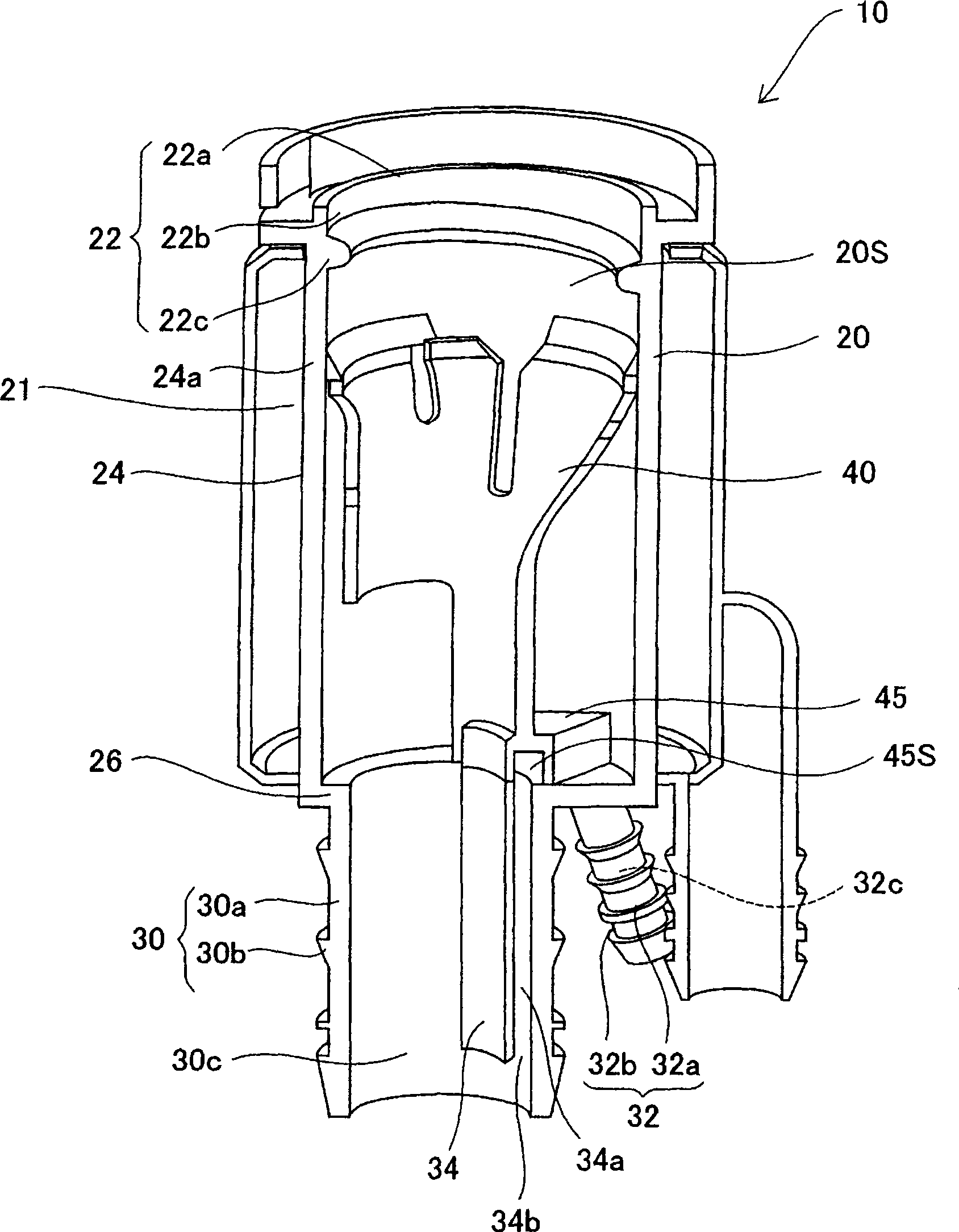
[0029] figure 1 It is a schematic configuration diagram showing a fuel supply device using a filler nozzle 10 according to an embodiment of the present invention. Such as figure 1 As shown, the filler nozzle 10 is disposed between the fuel inlet tank IB and the fuel tank FT, and delivers fuel supplied from a fuel supply gun (not shown) to the fuel tank FT. The filling port of the filler nozzle 10 is opened and closed by the fuel cap FC, and the downstream side of the filler nozzle 10 is connected to the fuel inlet pipe IT and the circulation pipe RT. The fuel inlet pipe IT conveys the fuel sprayed from the fuel supply gun from the fuel filler nozzle 10 to the fuel tank FT. The circulation pipe RT constitutes a part of a circulation passage which allows the fuel vapor-containing air of the fuel tank FT supplied with fuel to escape f...


PUM


Abstract

The invention provides a filler neck which can form recirculation passage and ensureing high seality by using simple structure. The filler neck 10 includes a neck tube body 20 having a fuel passage 30c; a guide member 40 for guiding the fuel gun and a recirculation passage that connects the fuel tank FT and the neck tube body through a passage separate from the fuel passage 30c, and that directs fuel vapors inside the fuel tank into the fuel passage 30c. The neck tube body includes a housing chamber 20S; a primary connector section 30 and a secondary connector section 32 connected to the housing chamber 20S and defining part of the recirculation passage. The guide member 41 is a member that is housed in the housing chamber and includes a guide section for guiding the fuel gun into the fuel passage and a passage-defining section 45 formed in the guide section, and partly defining the recirculation passage inside the housing chamber.

Description

technical field [0001] The invention relates to a filler nozzle for leading fuel into a fuel tank. Background technique [0002] Currently, the technology in Patent Document 1 is known as a fuel supply device having such a filler nozzle. That is, the fuel supply device has a fuel filler pipe and a guide part that is partially inserted into the fuel filler pipe and guides a fuel filler gun. The guide portion has a mechanism for holding the cover portion, and is fixed to the flange of the spout so that it is attached with a part of it inserted into the filler pipe. In addition, a return pipe is provided on the outer peripheral portion of the filler pipe. The return pipe constitutes a circulation passage by connecting the fuel tank to the fuel passage in the filler pipe, and functions to prevent air containing fuel vapor from being discharged to the outside during refueling. [0003] However, the conventional oil supply device has a breather portion between the oil filling p...

Claims


Application Information

Patent Timeline
Patent Type & Authority Applications(China)
IPC IPC(8): B60K15/04
CPCB60K15/04
Inventor 波贺野博之
Owner TOYODA GOSEI CO LTD
Learn More