Plasma display and driving method
A plasma and display technology, applied to static indicators, instruments, etc., can solve the problem of increasing the number of power supplies, achieve stable operation, and reduce the number of power supplies
Inactive Publication Date: 2010-12-01
SAMSUNG SDI CO LTD
View PDF1 Cites 0 Cited by
- Summary
- Abstract
- Description
- Claims
- Application Information
AI Technical Summary
Problems solved by technology
Consequently, separate power supplies are required to supply various voltages, increasing the number of power supplies
Method used
View moreImage
Smart ImageViewing Examples

Examples
Embodiment Construction
Login to view more PUM
 Abstract
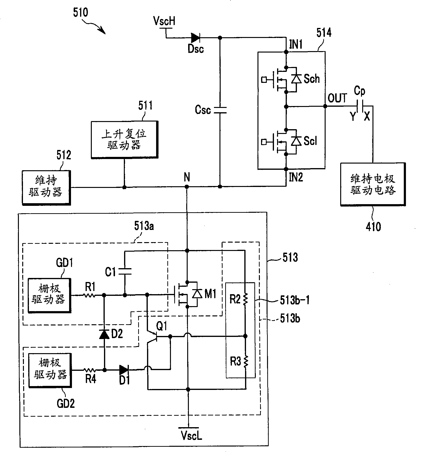
Provided is a plasma display device and drive method thereof. In a plasma display device, a first transistor is connected between an electrode and a power source supplying a first voltage, and a second transistor is connected to a control terminal of the first transistor. A first gate driver supplies a first control signal to the control terminal of the first transistor and is connected to the control terminal of the first transistor. A second gate driver supplies a second control signal to the second transistor, and is connected to the control terminal of the second transistor. Further, a diode is connected between an output terminal of the second gate driver and the control terminal of the first transistor.
Description
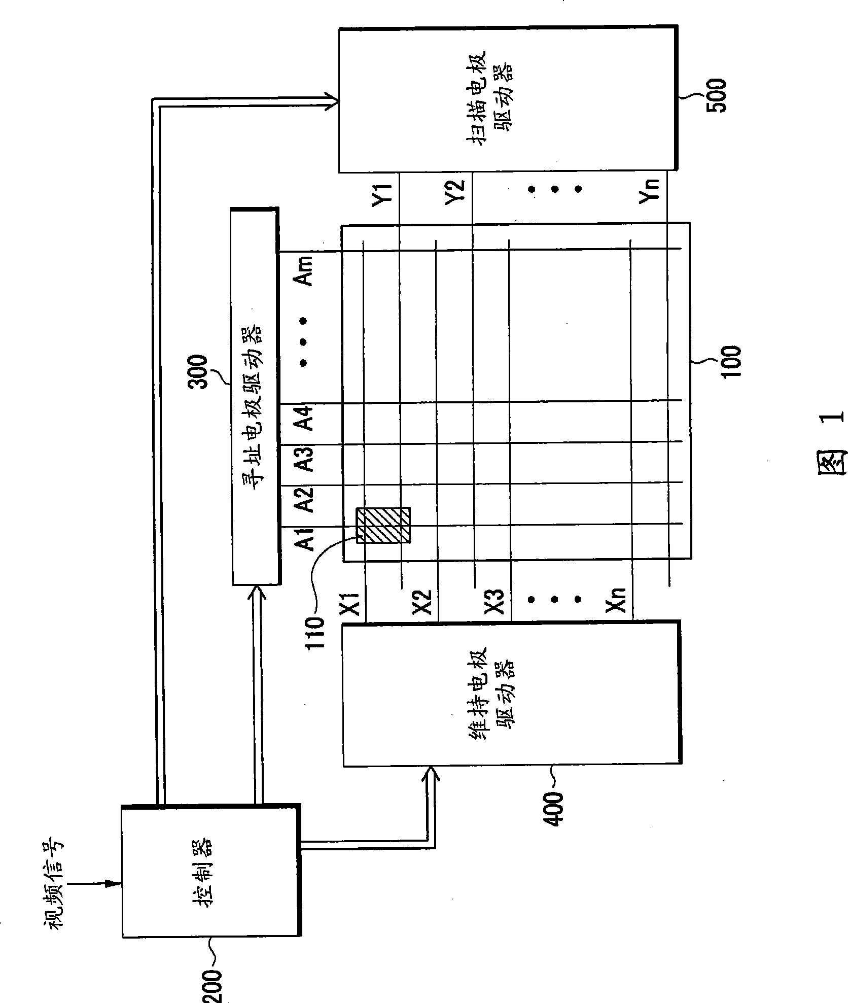
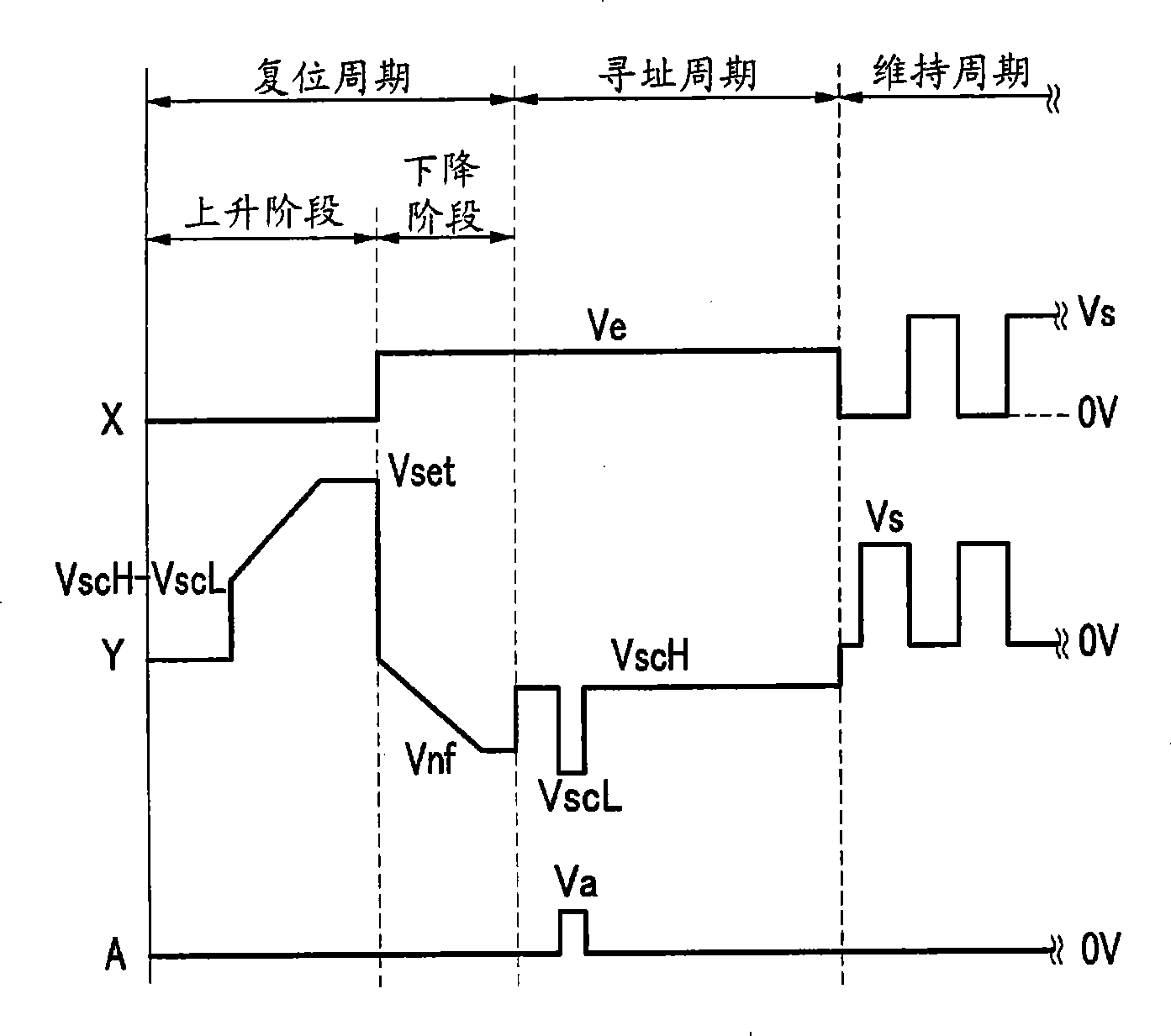
Plasma display and its driving method technical field Embodiments of the present invention relate to a plasma display device and a driving method thereof. Background technique A plasma display panel (PDP) is a flat panel display that displays characters or images using plasma generated by gas discharge. The PDP includes a plurality of discharge electrode pairs and a plurality of address electrodes intersecting the plurality of discharge electrode pairs. The plasma display device divides one frame into a plurality of subfields, each of which has a weighted value of luminance, and displays gray levels by combining the weighted values of subfields that generate a display operation among the plurality of subfields. Light-emitting cells and non-light-emitting cells are selected by address discharge during the address period of each subfield, and an image is actually displayed by performing sustain discharge in the light-emitting cells during the sustain period. A sustain ...
Claims
Login to view more Application Information
Patent Timeline
 Patent Type & Authority Patents(China)
IPC IPC(8): G09G3/28G09G3/288G09G3/292G09G3/296
CPCG09G2310/066G09G3/2927G09G3/296
Inventor 李相九
Owner SAMSUNG SDI CO LTD
- R&D Engineer
- R&D Manager
- IP Professional
Why Eureka
- Industry Leading Data Capabilities
- Powerful AI technology
- Patent DNA Extraction
Try Eureka
Browse by: Latest US Patents, China's latest patents, Technical Efficacy Thesaurus, Application Domain, Technology Topic.
© 2024 PatSnap. All rights reserved.Legal|Privacy policy|Modern Slavery Act Transparency Statement|Sitemap