rf ion source device

An ion source and plasma technology, which is applied in the field of ion source devices, can solve the problems of increased operation risk, higher requirements for power supply and components, complex structure, etc., and achieves the effects of reducing the number of power supplies, reducing complexity, and increasing safety.

Active Publication Date: 2019-07-05
KINGSTONE SEMICONDUCTOR LIMITED COMPANY
View PDF1 Cites 0 Cited by
  • Summary
  • Abstract
  • Description
  • Claims
  • Application Information

AI Technical Summary

Problems solved by technology

[0008] The technical problem to be solved by the present invention is to overcome that the ion source device in the prior art includes multiple components, multiple power sources, control devices and communication devices, complex structure, high requirements for various power sources and components, and When the ion source device needs to be raised to a high potential as a whole, thereby increasing the risk of operation, a RF ion source device is provided, which has a simple structure and does not need to be equipped with multiple power sources, and RF generators, matching devices and other equipment are all in the Working on the ground potential, only the plasma is raised to a high potential, which reduces the requirements for various components in the ion source device, and the protection of the capacitor blocking DC increases the safety of operation

Method used


Image

  • rf ion source device
  • rf ion source device
  • rf ion source device

Examples


Embodiment 1

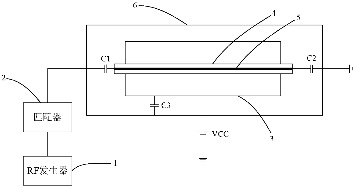
[0042] refer to figure 2, the RF ion source device described in this embodiment includes an arc cavity 3, the arc cavity is filled with gas, and at least one antenna 5 is placed in the arc cavity 3 (in this embodiment, an antenna is used For example), the antenna is arranged in an insulating sleeve 4, and the insulating sleeve 4 is made of quartz material, and the ion source device also includes a high-voltage power supply VCC, an RF generator 1, and a RF generator 1 connected to the The matcher 2 and the first capacitor C1 and the second capacitor C2,

[0043] Wherein, the first capacitor C1 is connected to the matcher 2 and the first end of the antenna ( figure 2 the left end of the middle antenna), the second end of the antenna ( figure 2 The right end of the middle antenna) is grounded through the second capacitor C2, the antenna 5 is used to emit electrons to generate plasma with the gas, and the high-voltage power supply VCC is connected to the arc cavity 3 so that ...

Embodiment 2

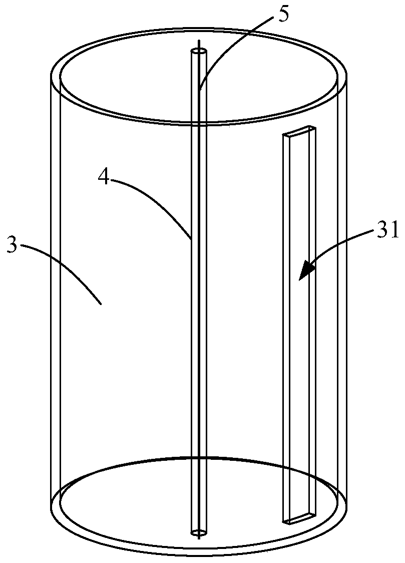
[0048] The principle of Embodiment 2 is the same as that of Embodiment 1, and the special point is that the reference image 3 In this embodiment, the appearance of the arc cavity is a cylinder, and the side wall of the arc cavity 3 is provided with a notch 31 , and the length direction of the notch 31 is parallel to the length direction of the antenna 5 . The notch 31 is used to draw out the beam current.

Embodiment 3

[0050] The basic principle of Embodiment 3 is the same as that of Embodiment 1, and the difference is that this embodiment also includes:

[0051] refer to Figure 4 ( Figure 4 The view is a top view, equivalent to starting from image 3 The RF ion source device also includes a plurality of magnetic devices 8 that generate a tangential magnetic field, which is used to cause the plasma in the arc cavity along the length of the antenna. The body is evenly distributed. In this embodiment, a plurality of magnetic devices 8 are arranged on the outer wall of the arc cavity 3, from Figure 4 From the top view direction shown, the distribution of the magnetic induction lines generated by the magnetic devices 8 that can cut the magnetic field is as follows: Figure 4 shown (in Figure 4 The magnetic induction line inside the arc cavity is represented by the reference symbol B).

[0052] Under the action of the shearing magnetic field, the plasma will be relatively uniform in the...


PUM


Abstract

Disclosed in the invention is an RF ion source apparatus comprising an arc cavity. The arc cavity is filled with gas; at least one antenna is arranged in the arc cavity; and each antenna is provided with an insulating casing tube. Besides, the ion source apparatus also includes a high-voltage power supply, an RF generator, a matcher connected with the RF generator, a first capacitor, and a second capacitor; the first capacitor is connected with the matcher and a first end portion of the antenna; and a second end portion of the antenna is grounded by the second capacitor. The antenna is used for an electron and the electron and the gas reacts to generate plasma; the high-voltage power supply is connected to the arc cavity, so that the level of the plasma is lifted to a preset level. The provided ion source apparatus has a simple structure; and arrangement of a plurality of power supplies is not required. Moreover, the RF generator, the matcher, and the communication control device and the like work at ground potentials, so that requirements on all components in the ion source apparatus are reduced and the operation security is improved.

Description

technical field [0001] The present invention relates to an ion source device, in particular to an RF (radio frequency) ion source device. Background technique [0002] The ion source device is one of the core components of ion implantation equipment. As a component that generates beam current, its performance has a crucial impact on the effect of ion implantation. If the beam drawn from the front-end ion source is not ideal (for example, the beam height is not uniform, the beam height is low, etc.), then the pressure of the downstream beam transmission system will be relatively large, and the non-ideal shape needs to be changed. The beam current is corrected to ideal injection conditions. On the contrary, if the beam drawn from the front end is ideal, the requirements for the downstream beam transmission system are reduced, and it is easier to achieve the ideal injection conditions, which is more conducive to the formation of high-quality beams. [0003] An existing ion so...

Claims


Application Information

Patent Timeline
Patent Type & Authority Patents(China)
IPC IPC(8): H01J37/317
Inventor 洪俊华杨勇张劲
Owner KINGSTONE SEMICONDUCTOR LIMITED COMPANY
Why Eureka
Try Eureka