Combined turn knob

A technology of knobs and knob seats, which is applied in the field of knobs, can solve problems such as monotonous structure of knobs and outdated styles, and achieve the effects of simple structure, low cost, and improved grade and competitiveness

Inactive Publication Date: 2009-04-22
胡杰波
View PDF1 Cites 5 Cited by
  • Summary
  • Abstract
  • Description
  • Claims
  • Application Information

AI Technical Summary

Problems solved by technology

However, the traditional knob structure is relat

Method used


Image

  • Combined turn knob
  • Combined turn knob
  • Combined turn knob

Examples


Example Embodiment

[0021] The present invention will be further described in detail below with reference to the embodiments of the accompanying drawings.

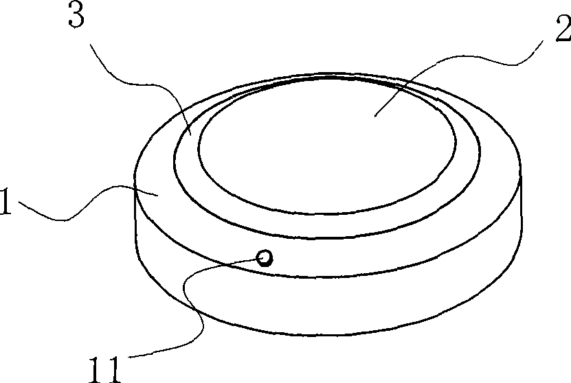
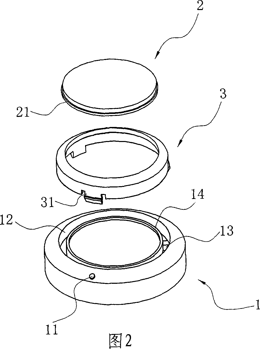
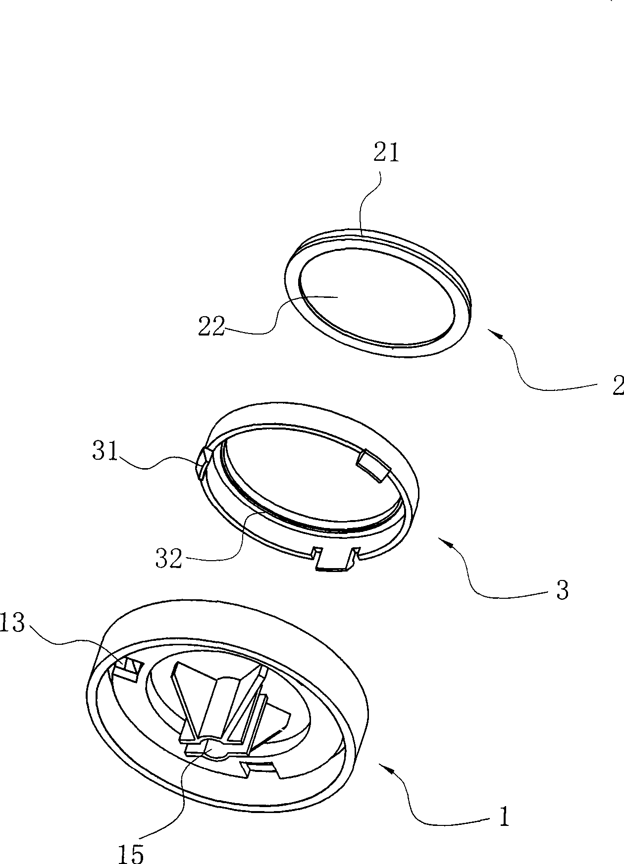
[0022] like Figure 1 to Figure 9 As shown in the figure, the combined knob is composed of a knob base 1, a transparent cover 2 and a connecting ring 3. Since the outline of the knob base of the combined knob is designed to be circular, the outlines of the transparent cover 2 and the connecting ring 3 in this embodiment are All are circular structures. Wherein, the lower surface of the knob seat 1 is conventionally provided with a shaft sleeve 15 which is matched with the switch or the timer shaft core, and the upper surface of the knob seat is provided with an annular groove 12, and the bottom of the annular groove 12 is spaced at regular intervals. There are three mounting holes 13; the above-mentioned transparent cover 2 is placed on the knob seat surrounded by the annular groove, the upper surface of the transparent cover 2 is an externa...


PUM


Abstract

A combined knob comprises a knob base, an annular groove is formed on the upper surface of the knob base, a transparent cover body is arranged on the knob base which is surrounded by the annular groove, the upper surface of the transparent cover body is an outer convex arc surface, the side surface of the transparent cover is extended to the outside to form a flange, thereby forming an outer step, a connecting ring is simultaneously arranged in the annular groove, an inner step which is buckled with the outer step is arranged on the connecting ring, and the connecting ring is connected with the knob base, thereby positioning the transparent cover body on the knob base. By adopting the above-mentioned structure, the combined knob can not only have beautiful visual style, but also be applicable to different devices by setting different patterns and textures; furthermore, as the transparent cover body is positioned in the middle part of the knob base, the patterns or the textures can occupy a larger proportion and be more complete, the combined knob simultaneously utilizes the role as a convex lens of the outer convex arc surface of the transparent cover body to lead the patterns or the textures to take on an amplification effect visually, and create an image of a crystal magic cube, thereby providing people with combined knobs with a greater variety.

Description

technical field [0001] The invention relates to a knob, in particular to a knob installed on a rotating shaft of a control part such as a switch or a timer. Background technique [0002] Along with the raising of people's living standard, various home appliances gradually become one of people's necessities of life. And every home appliance product without remote control is inseparable from the setting of control parts such as switches and timers. Each control part usually includes a control part body and a knob. The knob is set on the shaft core through the cooperation between the shaft sleeve and the shaft core. When in use, the shaft core can be driven to rotate by rotating the knob, and then can control the on or off of the switch, the timing of the timer and the selection of the program. . [0003] In order to facilitate operation, the above-mentioned knob is usually located in a conspicuous position of the home appliance. However, the traditional knob structure is re...

Claims


Application Information

Patent Timeline
IPC IPC(8): H01H19/14H01H19/04
Inventor 胡杰波
Owner 胡杰波
Why Eureka
Try Eureka