
High voltage power switch

A circuit breaker and power technology, applied in high-voltage air circuit breakers, high-voltage/high-current switches, circuits, etc., can solve problems such as no longer reliable

Inactive Publication Date: 2009-05-06
GENERAL ELECTRIC TECH GMBH
View PDF0 Cites 6 Cited by
  • Summary
  • Abstract
  • Description
  • Claims
  • Application Information

AI Technical Summary

Problems solved by technology

As a result, the two insulating gas streams, which are guided from two directions approximately along the longitudinal axis in the direction of the main current contacts outside the insulating material nozzle, may no longer have sufficient insulating capacity, so that in the high-voltage power circuit breaker Electrical separation of the two main current contacts may no longer be guaranteed in the aforementioned states of
In particular, there is the possibility that at least one of the two insulating gas flows flowing into the region of the two main current contacts consists of an insulating gas which is at least heated in such a way that it is no longer reliably possible to obtain a connection between the two main current contacts. electrical separation

Method used


Image

  • High voltage power switch
  • High voltage power switch

Examples


Embodiment Construction

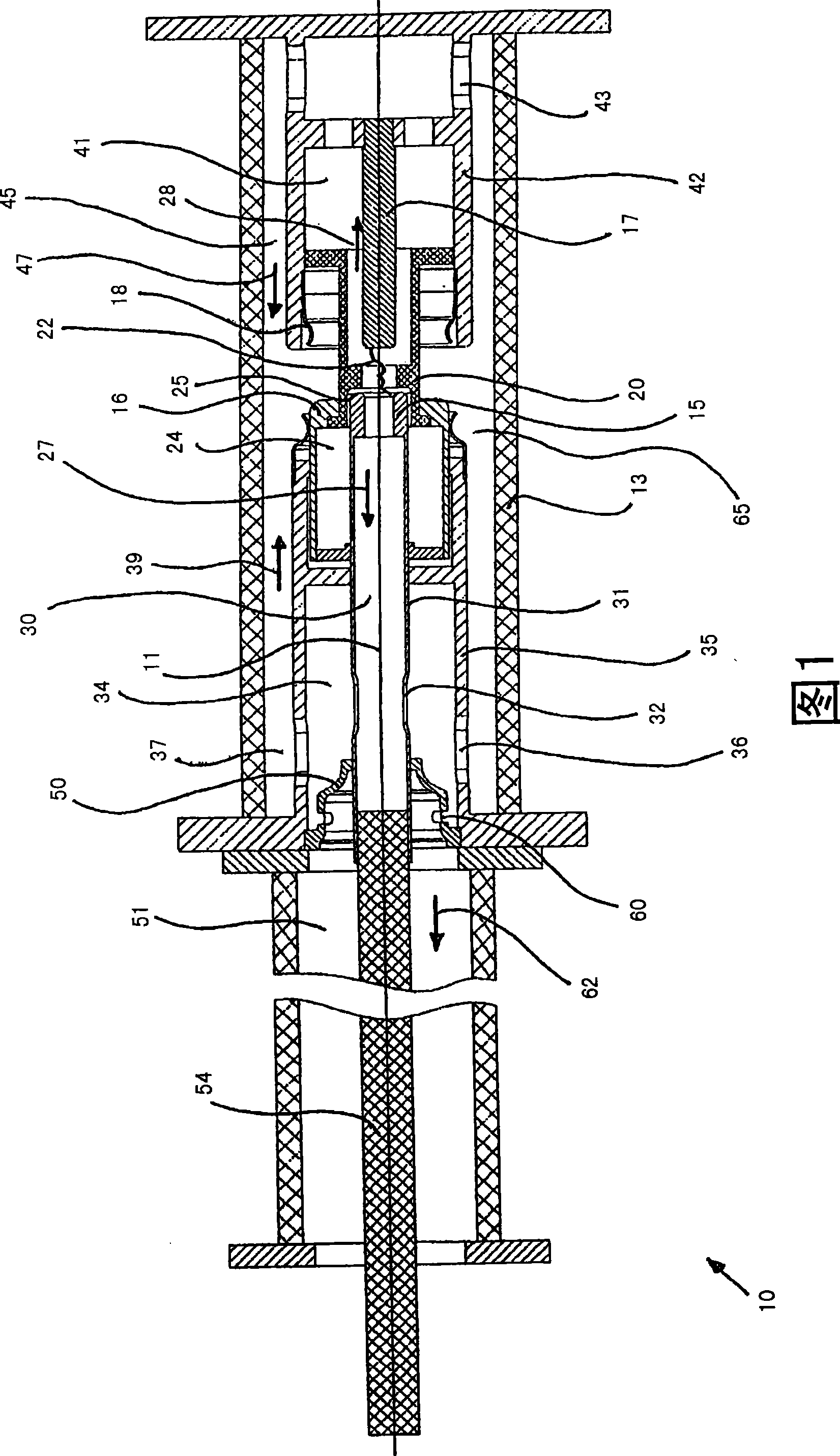
[0022] FIG. 1 shows a high-voltage power circuit breaker 10 , which has a longitudinal axis 11 and is substantially rotationally symmetrical. A quincunx-shaped arcing contact piece 15 with an associated first main current contact piece 16 and a pin with an associated second main current contact piece 18 are accommodated in an interior space of the porcelain housing 13 filled with insulating gas. Shaped arcing contacts 17. Sulfur hexafluoride (SF6) or nitrogen (N2) or tetrafluoromethane (CF4) or mixtures thereof can be used here as insulating gas.

[0023] The main current contacts 16 , 18 are arranged radially outside the arcing contacts 15 , 17 . The contact pieces 15 , 16 as well as the contact pieces 17 , 18 are oriented coaxially relative to one another and can each be moved together in the direction of the longitudinal axis 11 relative to one another, to be precise from a shorted, thus connected, end position to a disconnected position. in the end position thus switched...


PUM


Abstract

Described is a high-voltage circuit breaker provided with two opposite-arranged arcing contacts, which are surrounded by an insulating nozzle. Furthermore provided are two main contacts, arranged opposite each other outside of the insulating nozzle, with respectively one of these contacts being assigned to one of the two arcing contacts. The high-voltage circuit breaker is provided, in at least one embodiment, with at least one device for diverting an insulating gas flow from the region between the two arcing contacts, wherein a respective insulating gas flow is conducted outside of the insulating nozzle and in the direction toward the main contacts. A diverting device is provided, which is equipped with a mechanism for diverting insulating gas from the insulating gas flow that is diverted from the region between the two arcing contacts, such that the two insulating gas flows moving from both directions toward the main contacts have approximately the same effect on the insulating gas that is present in the region of the two main contacts, thereby ensuring that the insulating gas is not displaced significantly in this region.

Description

technical field [0001] The invention relates to an insulating gas-filled high-voltage power circuit breaker, which comprises: two arcing contacts facing each other, which are surrounded by a nozzle of insulating material; main current contacts facing each other outside the nozzle, each of which is assigned to one of the two arcing contacts; A device for leading off the region between the insulating material nozzles, wherein a flow of insulating gas is guided in each direction from two directions outside the insulating material nozzle in the direction of the main current contacts. Background technique [0002] Such high voltage power circuit breakers are generally known. The device for conducting the insulating gas flow from the area between the two arcing contacts has the task of conducting the insulating gas heated and expanded by the arc into other areas of the high-voltage power circuit breaker. In this way, not only can the hot insulating gas be decompressed, but it is...

Claims


Application Information

Patent Timeline
Patent Type & Authority Applications(China)
IPC IPC(8): H01H33/90
CPCH01H33/74
Inventor L·德鲁兹G·西里尔
Owner GENERAL ELECTRIC TECH GMBH
Learn More