Ergonomic configurations for thermal imaging cameras

A thermal imager, imager technology, applied in the direction of instruments, measuring devices, scientific instruments, etc., can solve the problem of not being able to fully utilize functional components

Active Publication Date: 2009-05-13
JOHN FLUKE MFG CO INC
View PDF1 Cites 3 Cited by
  • Summary
  • Abstract
  • Description
  • Claims
  • Application Information

AI Technical Summary

Problems solved by technology

However, there are situations in which users of such imagers cannot take full advantage of the imager's growing capabilities, such as when one of the user's hands must be used to stabilize the user at the inspection site without helping to hold and / or or when operating the imager

Method used


Image

  • Ergonomic configurations for thermal imaging cameras
  • Ergonomic configurations for thermal imaging cameras
  • Ergonomic configurations for thermal imaging cameras

Examples


Embodiment Construction

[0037] The following description is explanatory in nature and does not limit the scope, application and configuration of the invention in any way. Rather, the following description merely provides an illustration of possible applications of representative embodiments of the invention.

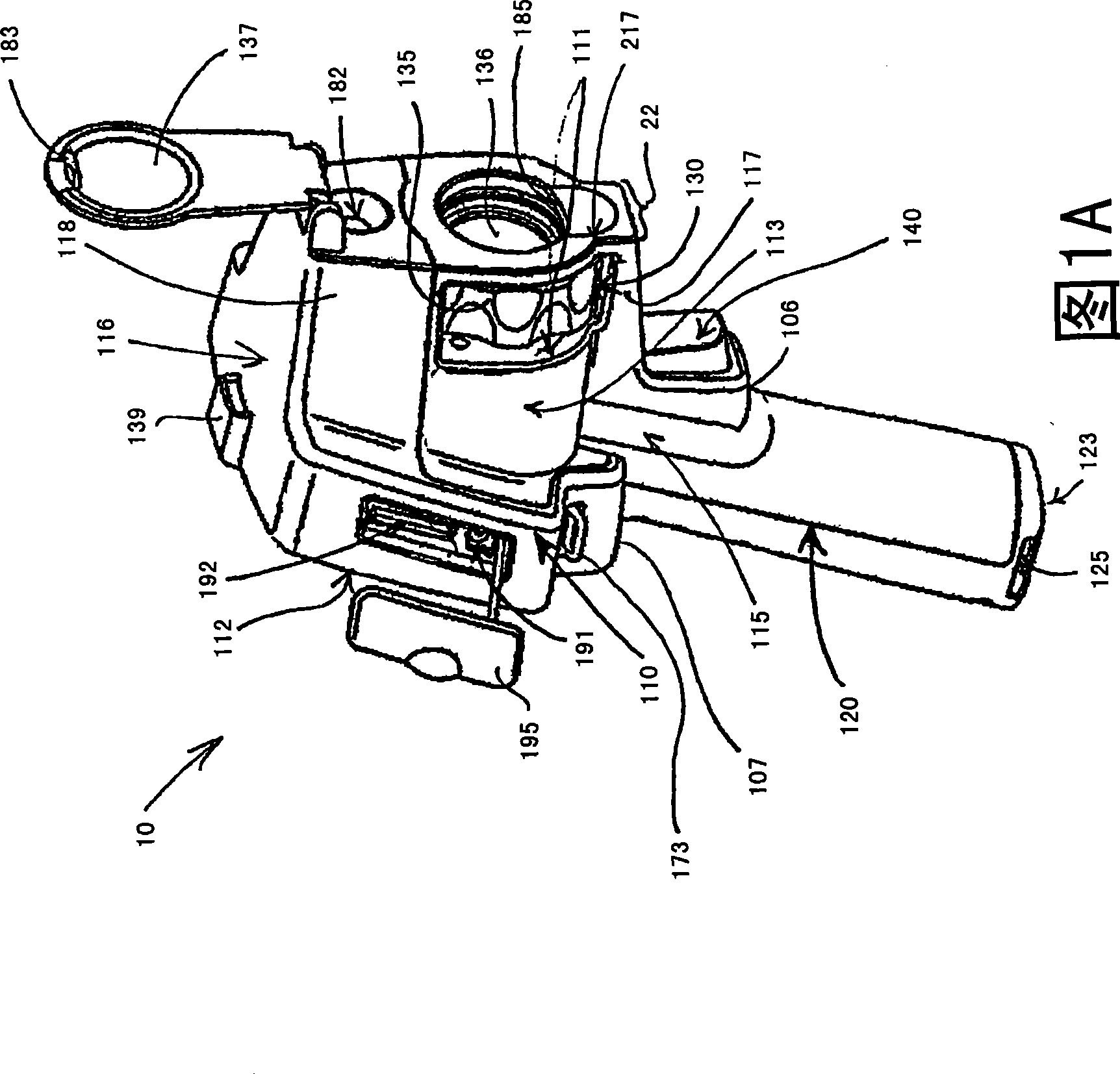
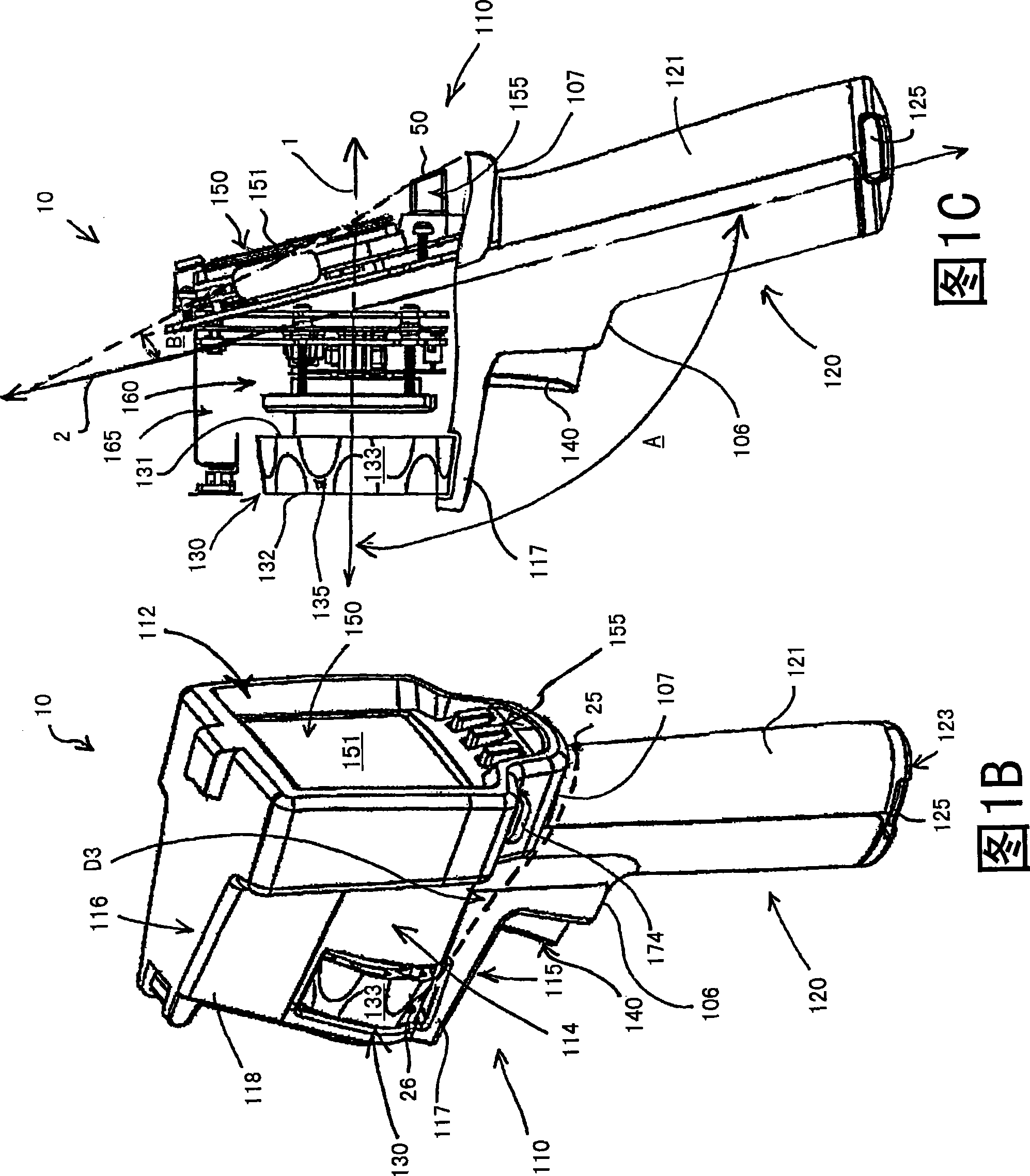
[0038] 1A-B are each a front perspective view of a thermal imager 10 according to some embodiments of the present invention. The housing of imager 10 is shown in FIGS. 1A-B and is formed of, for example, one or more injection-molded hard plastic pieces for all that is required in imager 10 for capturing infrared and visible light images. Components provide structural support for individual components that produce an ergonomic user interface. The imager portion 110 of the housing is shown to include a first side 111 , a second side 112 opposite the first side 111 , a third side 113 , a fourth side 114 opposite the third side 113 , a bottom side 115 and a top side. Side 116; the handle portion ...


PUM


Abstract

A housing of a thermal imaging camera includes a camera portion, in which an thermal imaging assembly is mounted, and to which a focusing assembly is mounted, on a first side thereof, and to which a display is mounted, on a second side thereof; a handle portion of the housing extends from a bottom side of the camera portion of the housing at an angle, away from the first side of the camera portion. The housing is configured for ergonomic handling wherein an index finger of a hand may readily activate the focusing assembly, when the hand is wrapped about the handle portion of the housing. The hand may be a right hand or a left hand, and the camera may further include additional features to provide support for single-handed operation.

Description

technical field [0001] The present invention pertains to thermal imagers, in particular their configuration for hand-held operation. Background technique [0002] For example, hand-held thermal imagers that include microbolometer-type detectors to produce infrared images are used in a variety of applications, including inspecting buildings and industrial facilities. Many thermal imagers in the prior art have a relatively large number of built-in features to allow the user to select a display mode from a variety of display options so that the user can maximize their understanding of the thermal performance information collected by the imager. Real-time or live understanding. However, there are situations in which users of such imagers cannot take full advantage of the imager's growing capabilities, such as when one of the user's hands must be used to stabilize the user at the inspection site without helping to hold and / or or when operating the imager. Therefore, there is a...

Claims


Application Information

Patent Timeline
IPC IPC(8): G01J5/00G01J5/02
CPCG01J5/0265G01J5/025H04N5/33G01J2005/0077H04N5/2252G01J5/04H04N23/51
Inventor J·M·希尔德J·V·弗兰特P·A·伯格斯特龙K·R·约翰逊C·W·拉格伯格F·Y·劳里诺M·E·洛库萨
Owner JOHN FLUKE MFG CO INC
Why Eureka
Try Eureka