Supercharge Your Innovation With Domain-Expert AI Agents!

Flasher mechanism

A flash device and light source technology, applied in the direction of lighting devices, optics, components of lighting devices, etc.

Inactive Publication Date: 2009-05-27
STANLEY ELECTRIC CO LTD
View PDF1 Cites 0 Cited by
  • Summary
  • Abstract
  • Description
  • Claims
  • Application Information

AI Technical Summary

Problems solved by technology

[0015] Furthermore, in Japanese Patent No. 3685516 Figure 8 In the flash device described, the reflected light reflected from the reflector to the right front side at a relatively large angle to the main optical axis of the flash device to the extent that it does not hit the right side wall of the light guide lens may be on the right side of the light guide lens. The exit (illumination) surface is totally reflected, and does not irradiate in the direction of illumination of the flash device (within the viewing angle)

Method used


Image

  • Flasher mechanism
  • Flasher mechanism
  • Flasher mechanism

Examples


Embodiment Construction

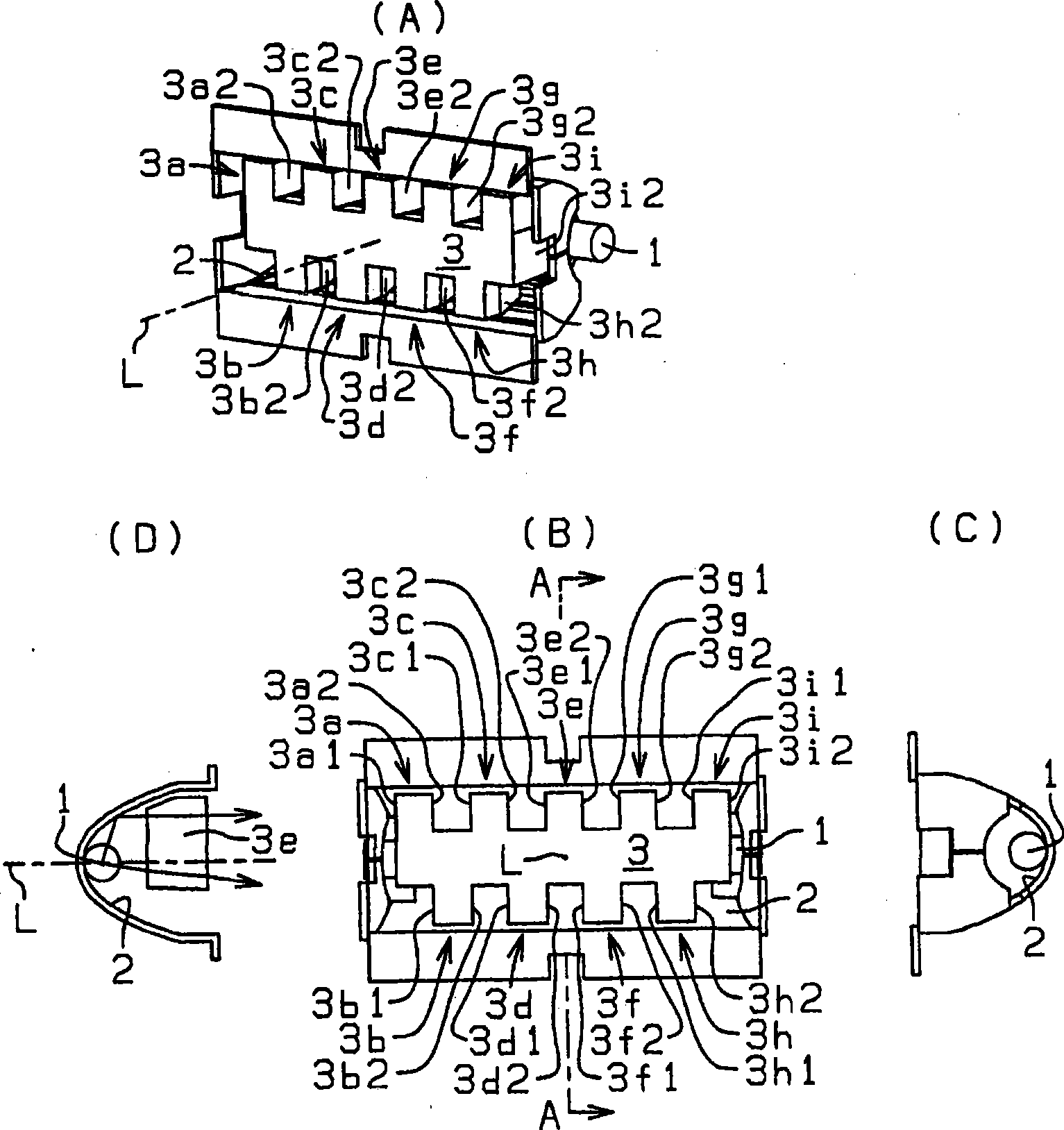
[0051] Hereinafter, a first embodiment of the flash device of the present invention will be described. figure 1 It is a figure which shows the flash device of 1st Embodiment. describe in detail, figure 1 (A) is a perspective view of the flash device of the first embodiment viewed from the right front side and the upper side, figure 1 (B) is a front view of the flash device of the first embodiment, figure 1 (C) is a right side view of the flash device of the first embodiment, figure 1 (D) is along figure 1 (B) Cross-sectional view of line A-A.

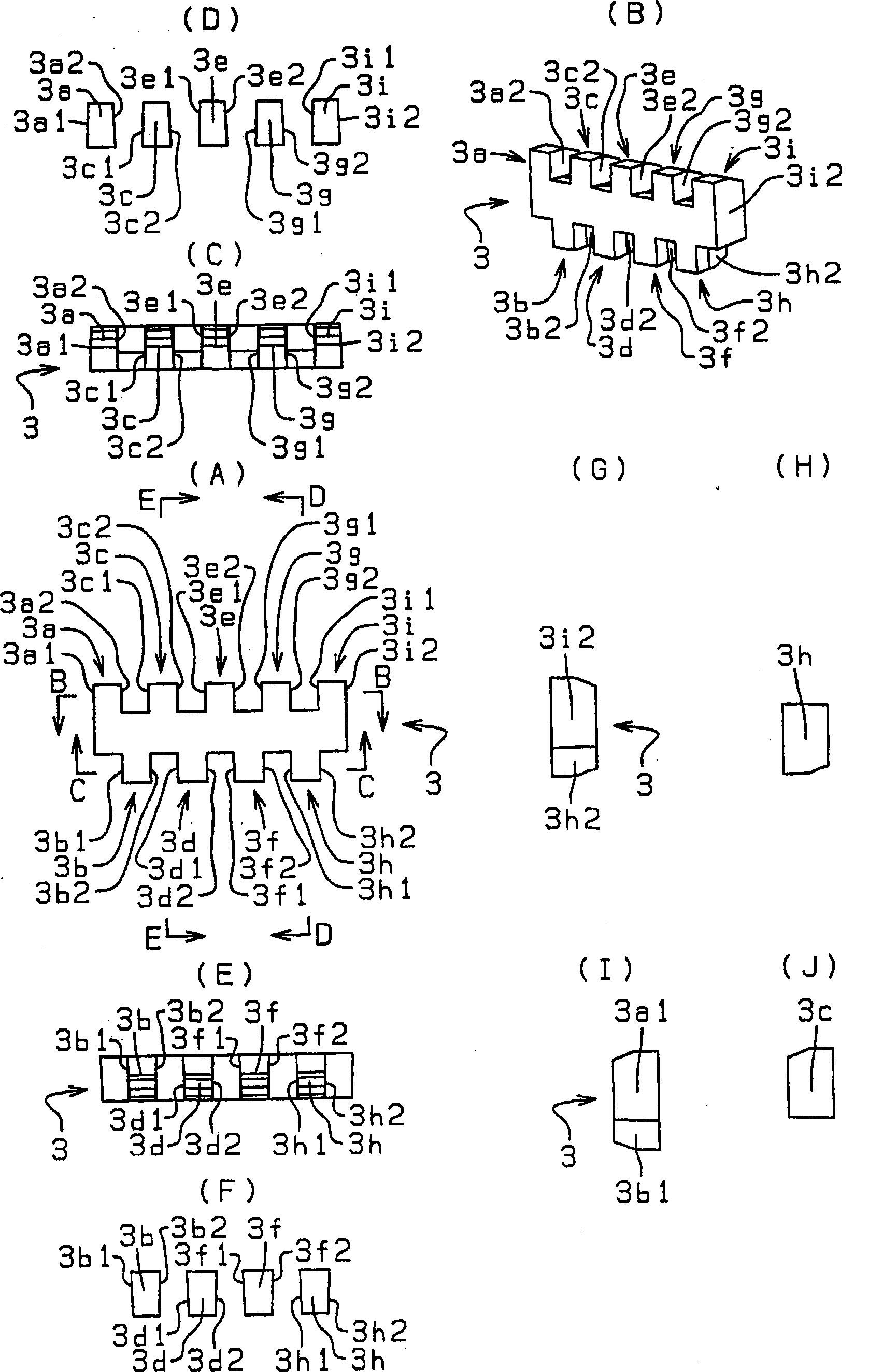
[0052] figure 2 Yes figure 1 A component diagram of the light guide lens 3 shown. describe in detail, figure 2 (A) is the front view of light guiding lens 3, figure 2 (B) is a perspective view of the light guide lens 3 viewed from the right front side and the upper side, figure 2 (C) is a top view of light guide lens 3, figure 2 (D) is along figure 2 (A) B-B line sectional view, figure 2 (E) is the bottom view...


PUM


Abstract

The invention provides a flash unit capable of increasing light irradiating in irradiation direction (in visual angle) of the flash unit. The flash unit includes: a tubular light source (1) extending in left and right directions; a reflection mirror (2) for reflecting light from a light source (1); a light guiding lens (3) for guiding direct light radiated from the light source (1) and / or light reflected by the reflection mirror (2) after being discharged from the light source (1), wherein the light guiding lens (3) is composed by dividing into a plurality of lens sections (3a-3i) arranged on left and right directions, walls (3a2-3i2) on right side extending to right side and extending forwards relative to a main light axis (L) of the flash unit, and walls (3a1-3i1) on left side extending to left side and extending forwards relative to a main axis (L) of the flash unit are arranged on the lens sections.

Description

technical field [0001] The present invention relates to a flash device having: a tubular light source extending in left and right directions; a reflection mirror for reflecting light emitted from the light source; and a light guide lens which guides direct light emitted from the light source and / or Or reflected light emitted from a light source and reflected by a reflector, particularly relates to a flash device capable of increasing the amount of light irradiated in the irradiation direction (within the viewing angle) of the flash device. [0002] In detail, the present invention relates to a flash device capable of reducing light including light that can be refracted on an exit (irradiation) surface of a light guide lens and directed in a direction (angle of view) that deviates from the irradiation direction of the flash device. outside) irradiated light, or light that is totally reflected by the exit (irradiation) surface of the light guide lens and does not irradiate to th...

Claims


Application Information

Patent Timeline
Patent Type & Authority Applications(China)
IPC IPC(8): G03B15/05F21V5/04
CPCF21V5/008F21V5/04
Inventor 安达刚内田大祐
Owner STANLEY ELECTRIC CO LTD
Features
  • R&D
  • Intellectual Property
  • Life Sciences
  • Materials
  • Tech Scout
  • Unparalleled Data Quality
  • Higher Quality Content
  • 60% Fewer Hallucinations
Learn More