Projector

a projector and projector technology, applied in the field of projectors, can solve the problems of significant deformation of the performance of the projection system, increased cost, image brightness reduction, etc., and achieve the effects of reducing manufacturing costs, increasing design freedom, and increasing degree of design freedom

Active Publication Date: 2010-07-01
SEIKO EPSON CORP
View PDF7 Cites 26 Cited by
  • Summary
  • Abstract
  • Description
  • Claims
  • Application Information

AI Technical Summary

Benefits of technology

[0027]It is preferable that the central portion has a substantially rectangular shape in the plan view, and the peripheral portions are connected only to a pair of sides of the central portion that face each other. Since the peripheral portions are connected only to a pair of sides of the central portion that face each other, the cover portion can be manufactured only by bending both sides of a flat plate having entirely flat surface, whereby the manufacturing cost can be reduced.
[0028]It is preferable that the central portion is substantially parallel to a predetermined flat surface of the outer surfaces of the housing. Since the central portion is substantially parallel to a predetermined flat surface of the outer surfaces of the housing, the projector can be designed with no constraint and the degree of design freedom can be increased as compared to, for example, a case where a dome-shaped cover portion is employed. Further, when the central portion is completely flush with the predetermined outer surface of the housing, the degree of design freedom can be increased, and the cover portion can be integrated with the housing. Integrating the cover portion with the housing contributes to cost reduction because the number of assembly steps and the number of parts are reduced. When the cover portion is integrated with the housing, only the cover portion can transmit light by forming the entire structure with a transparent member and painting the portion other than the cover portion.
[0029]It is preferable that each of the peripheral portions is substantially parallel to a predetermined flat surface of the outer surfaces of the housing. Since each of the peripheral portions is substantially parallel to a predetermined flat surface of the outer surfaces of the housing, the projector can be designed with no constraint and the degree of design freedom can be increased as compared to, for example, a case where a dome-shaped cover portion is employed. Further, when each of the peripheral portions is completely flush with the predetermined outer surface of the housing, the degree of design freedom can be increased, and the cover portion can be integrated with the housing. Integrating the cover portion with the housing contributes to cost reduction because the number of assembly steps and the number of parts are reduced. When the cover portion is integrated with the housing, only the cover portion can transmit light by forming the entire structure with a transparent member and painting the portion other than the cover portion.
[0030]It is preferable that the projection unit includes a wide-angle light forming reflector that forms wide-angle light. In a projector including a wide-angle light forming reflector, that is, a proximity projection-type projector, when combined with a cover portion of related art, the reflection off the light-incident surface of the cover portion significantly reduces image brightness. The cover portion according to the aspect of the invention having bent peripheral portions can reduce the angle of incidence of the projection light, reduces the reflectance of the light-incident surface at which the projection light is reflected, and prevents decrease in image brightness.
[0031]It is preferable that the cover portion is inclined in such a way that the surface of the central portion through which the projection light exits faces the illuminated surface. Since a proximity projection-type projector is installed below the screen, the projection light exits through a top portion of the housing and travels toward the screen obliquely to some extent. Since the projection light is thus inclined, the angle of incidence of the projection light incident on the light-incident surface of the cover portion increases. Since the cover portion according to the case described above is inclined in such a way that the surface through which the projection light exits faces the screen, the inclination of the cover portion can cancel the increase in the angle of incidence of the projection light incident on the light-incident surface of the cover portion due to the inclination of the projection light. Therefore, simply inclining the cover portion can prevent the decrease in image brightness.
[0032]It is preferable that the peripheral portions are bent and inclined to the central portion by approximately 90 degrees. Since the peripheral portions are bent and inclined to the central portion by approximately 90 degrees, the cover portion can be a compact structure in which only small overhangs jut out from the central portion in the plan view. This structure also contributes to the compactness of the projector. In a proximity projection-type projector, in particular, the wide-angle projection light requires a large, wide cover portion to transmit all the projection light when the cover portion is entirely flat. In the case described above, since the peripheral portions are bent and inclined to the central portion by approximately 90 degrees, all the projection light can be transmitted and the cover portion can be compact at the same time.

Problems solved by technology

The performance of the projection system is significantly degraded in some cases due to dust, dirt, and other factors.
Therefore, among the projection light incident on the cover portion, the projection light incident at a large angle of incidence disadvantageously forms an image having reduced brightness.
In this case, however, a significantly large number of coating layers is required to achieve an anti-reflection capability across a wide range of angle of incidence, resulting in increase in cost.
Therefore, a proximity projection-type projector, in particular, suffers from significant reduction in image brightness due to the angle of incidence of the light incident on the cover portion.
In this case, however, the anti-reflection and other processes are complicated, and the cost disadvantageously increases.
Therefore, the cover portion can not only protect the projection unit from dust and dirt but also, for example, prevent the decrease in brightness of an image displayed on a screen, which is the illuminated surface.
Further, since the projection light is incident on the central portion of the cover portion at a small angle of incidence in a projector in many cases, a problem of the decrease in image brightness will unlikely occur even when the central portion is formed of a flat surface.

Method used


Image

  • Projector
  • Projector
  • Projector

Examples


first embodiment

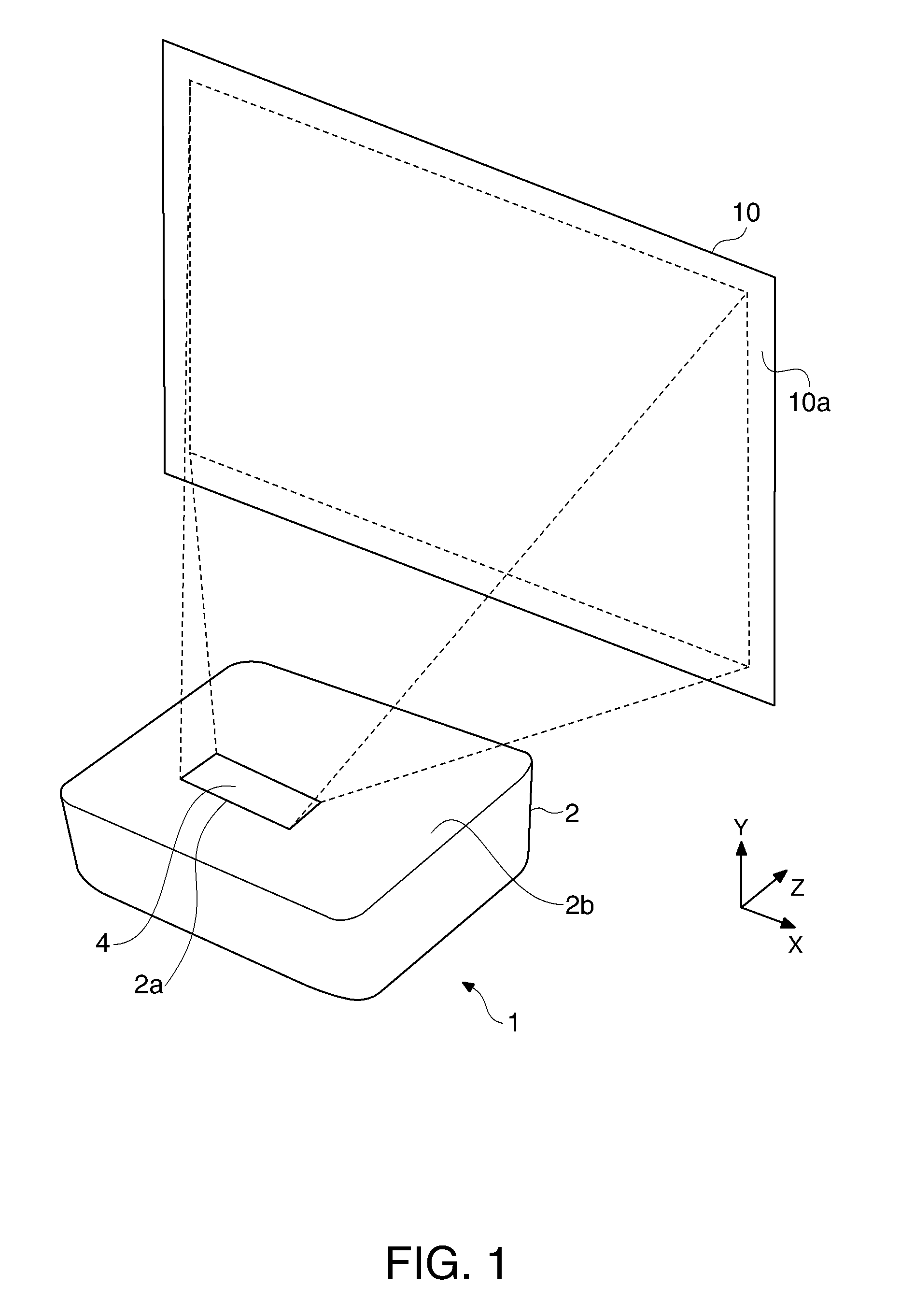
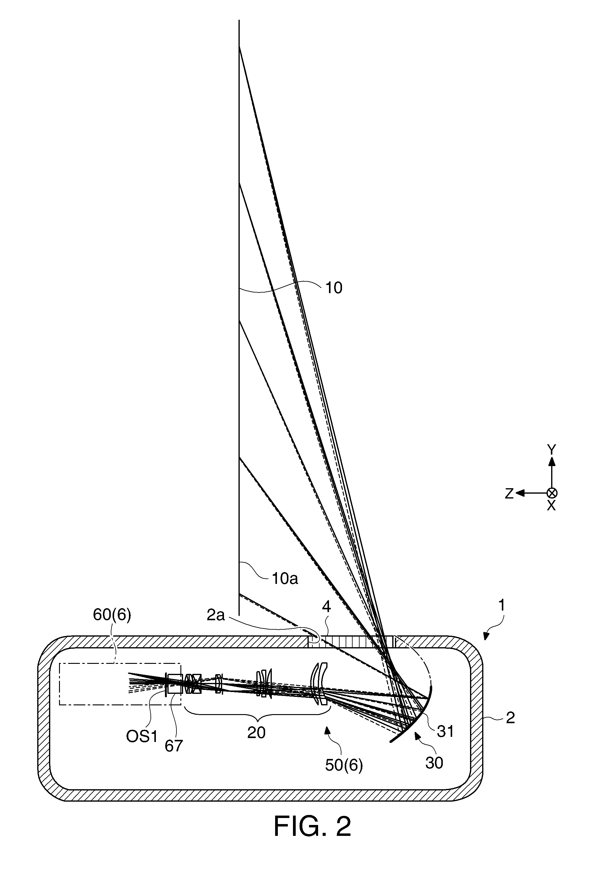
[0065]FIG. 1 is a perspective view showing how a projector according to a first embodiment of the invention is used. FIG. 2 is a transverse cross-sectional view showing a schematic configuration of the interior of the projector. FIG. 3 is a front cross-sectional view but does not show the interior configuration of the projector. The projector 1 is a front projection-type projector that projects projection light on a screen 10 to display an image. A viewer observes the image displayed on the screen 10. The projector 1 is a proximity projection-type projector that is positioned in the vicinity of the screen 10 and projects wide-angle projection light on the screen 10 to display an image.

[0066]The screen 10 is a reflective projection plate and diffuses and reflects the light incident on a front-side screen projection surface (illuminated surface) 10a to display an image. The axis along a normal to the screen projection surface 10a is called a Z axis. The axes perpendicular to the Z axi...

second embodiment

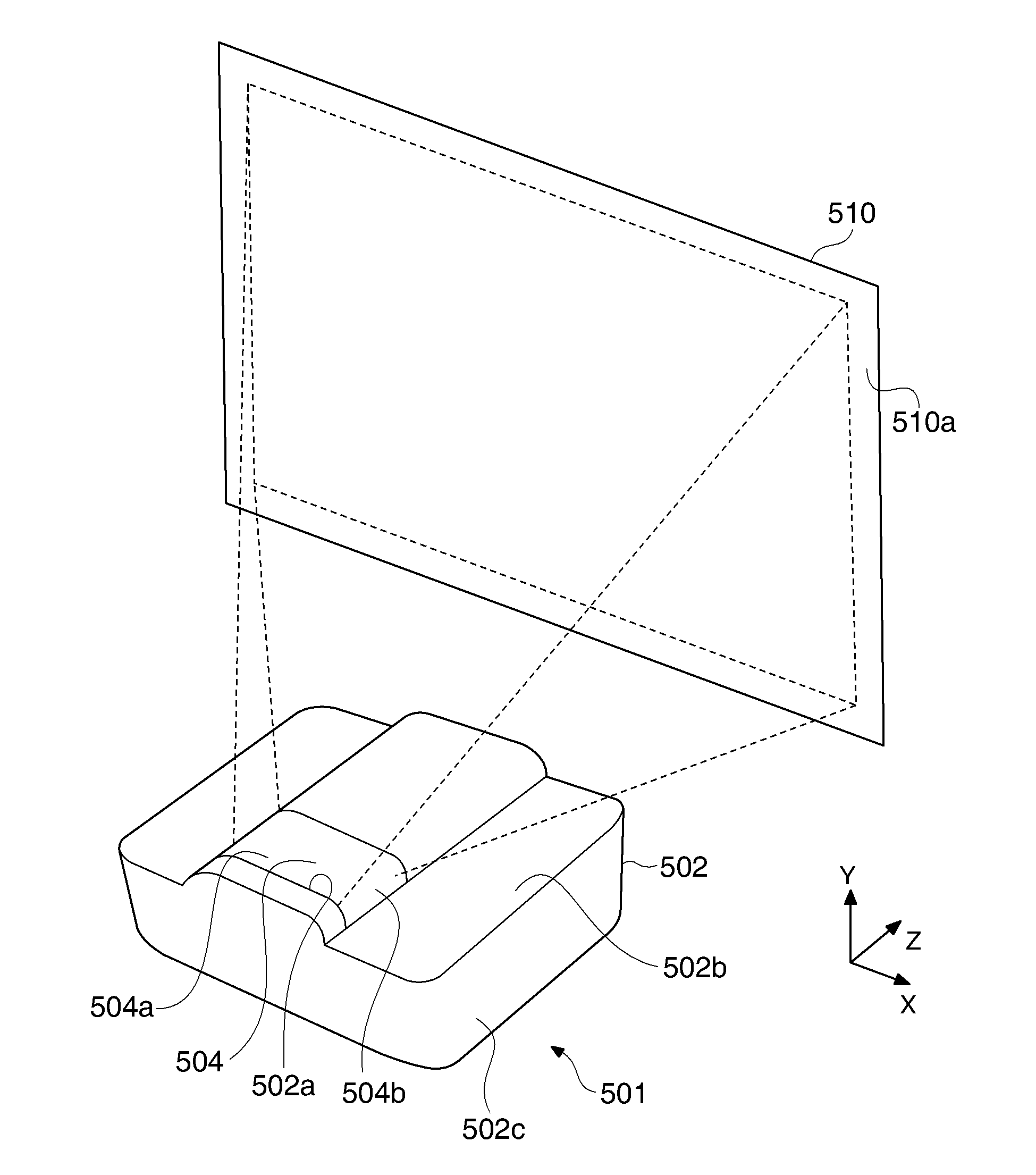
[0104]FIG. 15 is a perspective view showing how a projector according to a second embodiment of the invention is used. FIG. 16 is a transverse cross-sectional view showing a schematic configuration of the interior of the projector. The projector 501 is a front projection-type projector that projects projection light on a screen to display an image. A viewer observes the image displayed on the screen. The projector 501 is a proximity projection-type projector that is positioned in the vicinity of a screen 510 and projects wide-angle projection light on the screen 510 to display an image.

[0105]The screen 510 is a reflective projection plate and diffuses and reflects the light incident on a front-side screen projection surface (illuminated surface) 510a to display an image. The axis along a normal to the screen projection surface 510a is called a Z axis. The axes perpendicular to the Z axis and intersecting each other at right angles are called an X axis and a Y axis.

[0106]The projecto...

third embodiment

[0133]FIG. 24 is an exterior perspective view of a projector 601 according to a third embodiment of the invention. The components that are the same as those in the second embodiment have the same reference characters, and no redundant description thereof will be made. The projector 601 according to the third embodiment is characterized in that the surface of a central portion 604a of a dust-proof cover 604 through which the projection light exits is inclined toward the screen 510. The projector 601 is further characterized in that peripheral portions 604b of the dust-proof cover 604 are bent and inclined to the central portion 604a by 90 degrees.

[0134]FIG. 25 is a partial enlarged view of a reflection optical unit (wide-angle light forming reflector) 630 provided in the projection system 550 of the projector 601. The reflection optical unit 630 includes a curved mirror 631. While the curved mirror 531 described in the second embodiment has a concave shape, the curved mirror 631 in t...


PUM


Abstract

A projector includes: a projection unit that projects projection light toward an illuminated surface; a housing that houses the projection unit and has an opening that allows the projection light to exit outward; and a cover portion that blocks the opening and transmits the projection light, wherein a plurality of areas is set in the cover portion relative to the projection unit, and a process of changing the reflectance of the light-incident surface of the cover portion at which the projection light is reflected is performed on each of the areas.

Description

BACKGROUND[0001]1. Technical Field[0002]The present invention relates a projector, and particularly to a technology of a projector including a cover portion that protects a projection unit.[0003]2. Related Art[0004]A projector that projects light on a screen to display an image includes a light projection system in a housing. The performance of the projection system is significantly degraded in some cases due to dust, dirt, and other factors. To protect the projection system from dust and dirt, a configuration in which the housing includes a light-transmissive cover portion has been proposed (see JP-A-2004-12749, JP-T-2008-522229, JP-A-2008-107801, and JP-A-2008-165202, for example).[0005]Most of the light projected from the projection system passes through the cover portion and is projected on the screen, but part of the light is reflected off the light-incident surface of the cover portion. The ratio of the amount of light reflected off the cover portion to the total amount of lig...

Claims


Application Information

Patent Timeline
Patent Type & Authority Applications(United States)
IPC IPC(8): G03B21/28G03B21/22
CPCG03B21/28G03B21/145
Inventor MORIKUNI, EIJIMINEFUJI, NOBUTAKA
Owner SEIKO EPSON CORP
Why Eureka
Try Eureka