Neckdown detection control method for arc welding of consumable electrode

A melting electrode, arc welding technology, applied in arc welding equipment, welding equipment, manufacturing tools, etc., can solve problems such as reducing sputtering

Active Publication Date: 2009-06-03
DAIHEN CORP
View PDF1 Cites 12 Cited by
  • Summary
  • Abstract
  • Description
  • Claims
  • Application Information

AI Technical Summary

Problems solved by technology

However, when the advance angle of the welding torch is increased, the principle of sputtering when the arc reoccurs changes, so only reducing the current value Ia at the time of arc reoccurrence cannot significantly reduce the occurrence of sputtering.

Method used


Image

  • Neckdown detection control method for arc welding of consumable electrode
  • Neckdown detection control method for arc welding of consumable electrode
  • Neckdown detection control method for arc welding of consumable electrode

Examples


Embodiment approach 1

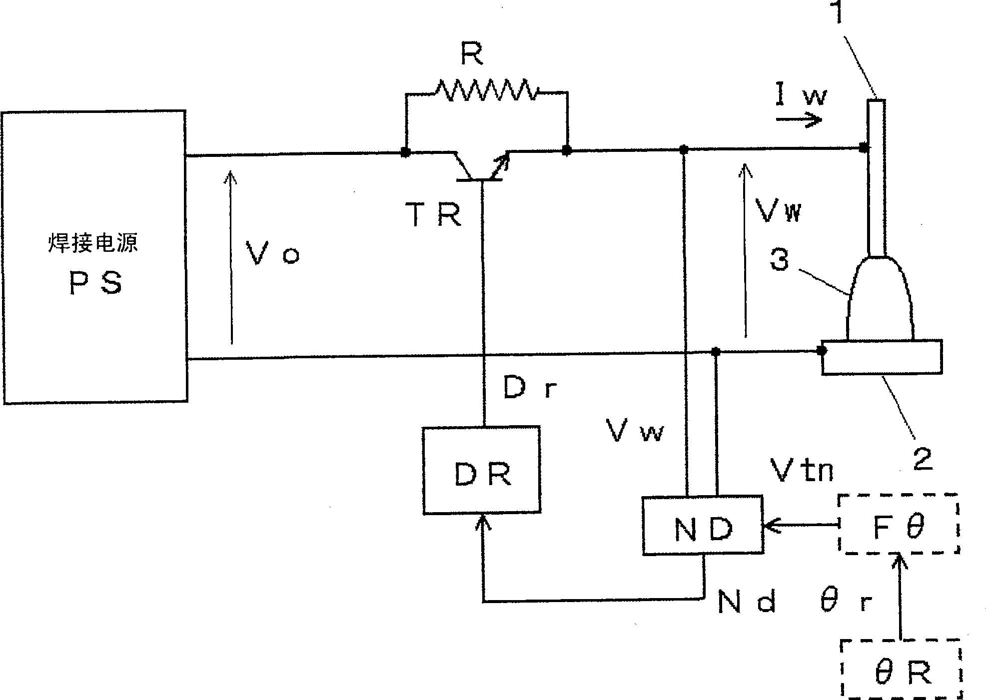
[0101] figure 1 It is a block diagram of a welding device for implementing the necking detection control method according to Embodiment 1 of the present invention. This figure is similar to the above Figure 9 Correspondingly, the same symbols are assigned to the same modules and their descriptions are omitted. Below, with reference to the accompanying drawings Figure 9 The different modules indicated by dashed lines are illustrated.

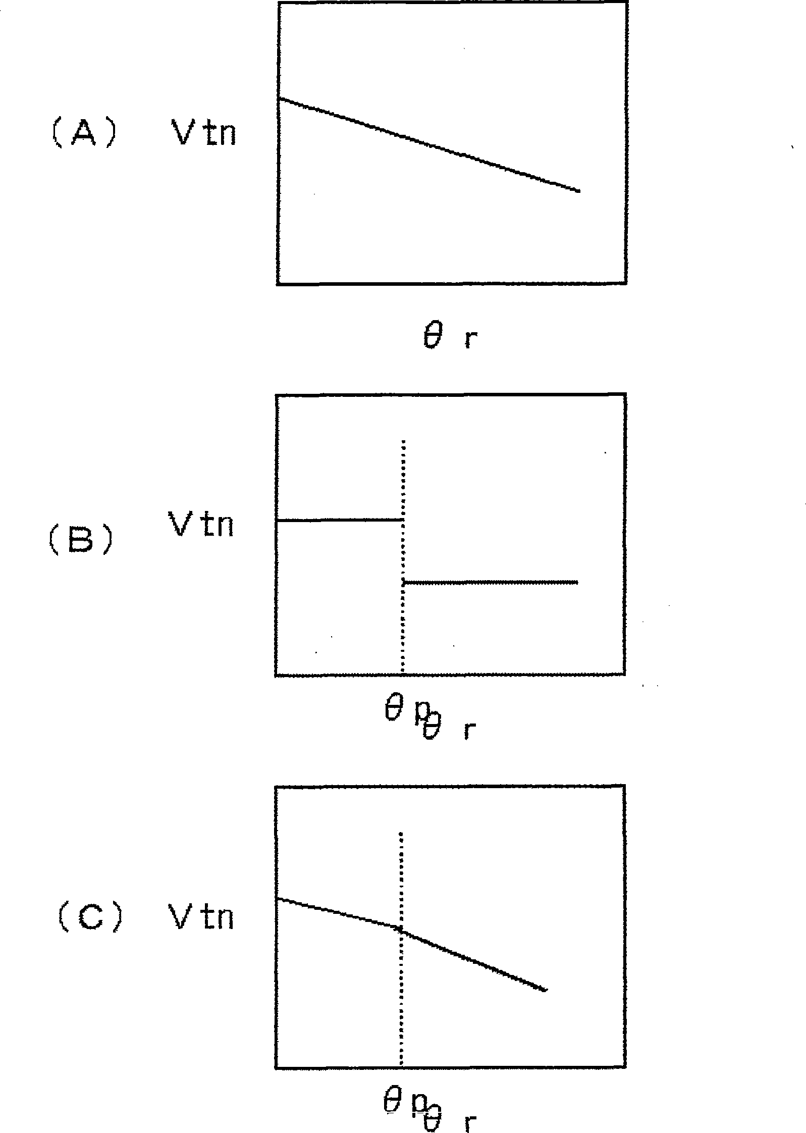
[0102] The advance angle setting circuit θR outputs a predetermined advance angle setting signal θr. The advance angle-corresponding constriction detection reference value setting circuit Fθ takes the advance angle setting signal θr as input, and calculates the constriction detection reference value signal Vtn by using a predetermined advance angle-corresponding constriction detection reference value setting function f(θr). value and output. Corresponding necking detection reference value setting function Vtn=f(θr) of this advancing angle...

Embodiment approach 2

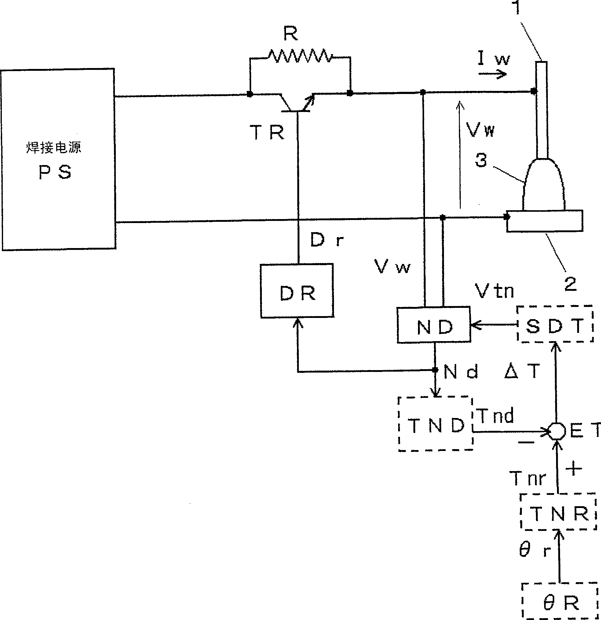
[0110] image 3 It is a block diagram of a welding device for implementing the necking detection control method according to Embodiment 2 of the present invention. In this figure against the above Figure 9 The same modules are assigned the same symbols and their descriptions are omitted. Below, yes and Figure 9 The different modules indicated by dashed lines are illustrated.

[0111] The constriction detection time detection circuit TND receives the constriction detection signal Nd as input, detects the constriction detection time Tn for each short circuit, calculates their average value, and outputs the constriction detection time detection signal Tnd.

[0112] The advance angle setting circuit θR outputs a predetermined advance angle setting signal θr. The advance angle corresponding constriction detection time setting circuit TNR takes the advance angle setting signal θr as input, and outputs the constriction detection time setting signal Tnr according to a predetermi...

Embodiment approach 3

[0120] Figure 5 It is a waveform diagram of a short-circuit current showing a constriction detection control method for molten electrode arc welding according to Embodiment 3 of the present invention. Figure (A) is a waveform diagram when the advancing angle of the welding torch is small, and Figure (B) is a waveform diagram when the advancing angle is large. The following description will be made with reference to this figure.

[0121] At time t1, when the droplet formed at the tip of the welding wire and the base metal are in a short-circuit state, the short-circuit current, which is the welding current energized by the short-circuit load, increases. As shown in the figure (A), when it is detected that the occurrence of necking in the droplet is detected at time t2, the short-circuit current suddenly decreases. When the arc occurs again at time t3, the welding current increases. The same applies to the case of the figure (B). However, in Embodiments 1 and 2, since the a...


PUM


Abstract

The neckdown detection control method for an arc welding of consumable electrode detects a necking formation of a molten drop by reaching a neckdown detection standard value V(tn) through the change of a voltage (Vw) between a molten electrode and a base metal, to make a welding current (Iw) to decrease rapidly to regenerate electric arc under a state of low current. When an advancing angle setting signal is increasing, the value of the neckdown detection standard value (Vtn) is reduced. Therefrom, it is able to detect neckdown rapidly due to higher neckdown detection sensitivity. The result is that the molten drop transition is end almost after regenerating the electric arc because the time from neckdown detection till regenerating the electric arc may be added, thus it is able to restrain sputtering, such that it is able to restrain the sputtering through detection of molten drop neckdown and rapid decrease of welding current during arc welding period. The effect of decreasing sputtering may be implemented even though the advanced angle is large.

Description

technical field [0001] The present invention relates to a necking detection control method for melting electrode arc welding for detecting the necking phenomenon of droplet during short circuit and reducing welding current suddenly to improve welding quality. Background technique [0002] Figure 8 It is a graph showing the current / voltage waveform and droplet transfer in the molten electrode arc welding of repeated short-circuit period Ts and arc period Ta. The figure (A) shows the time change of the welding current Iw energized to the melting electrode (hereinafter referred to as welding wire 1), and the figure (B) shows the time change of the welding voltage Vw applied between the welding wire 1 / base metal 2, and the figure ( C) to (E) show the state of transition of the droplet 1a. The following description will be made with reference to this figure. [0003] During the short-circuit period Ts from time t1 to time t3, the droplet 1a at the tip of the welding wire 1 is ...

Claims


Application Information

Patent Timeline
Patent Type & Authority Applications(China)
IPC IPC(8): B23K9/00B23K9/10
Inventor 井手章博
Owner DAIHEN CORP
Why Eureka
Try Eureka