Method for spatial-frequency filtering and imaging apparatus

An image capture, spatial frequency technology, applied in the field of film cameras and image capture equipment, can solve the problems of low light sensitivity, immutability, and increased data processing requirements.

Inactive Publication Date: 2009-06-10
格尔德·斯图克勒
View PDF3 Cites 0 Cited by
  • Summary
  • Abstract
  • Description
  • Claims
  • Application Information

AI Technical Summary

Problems solved by technology

However, this solution leads to a lower light sensitivity, since in sensors with multiple pixels the effective light-sensitive area of ​​the sensor is reduced due to the necessary leads (Zuleitung) on ​​the sensor, since the sensor requires each pixel to remain the same size the area of
Furthermore, this solution leads to increased data processing requirements and thus to the consequent necessity to use high-efficiency electronics with increased energy requirements
[0011] Another disadvantage of the known optical pre-filter is that the change or configuration of the filter curve is fixed and unchangeable.

Method used


Image

  • Method for spatial-frequency filtering and imaging apparatus
  • Method for spatial-frequency filtering and imaging apparatus
  • Method for spatial-frequency filtering and imaging apparatus

Examples


Embodiment Construction

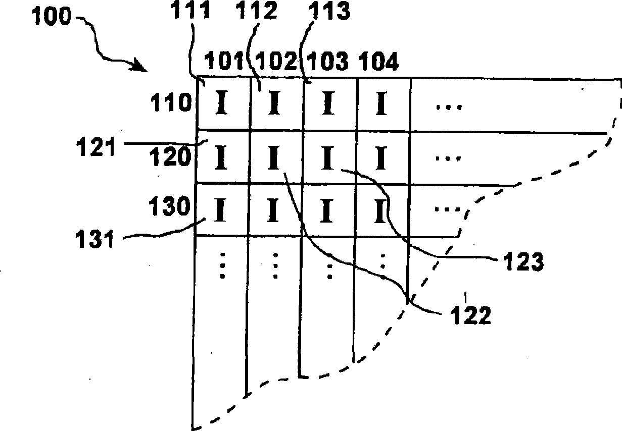
[0045] Figure 1a A section of the first image sensor 100 is schematically shown. The image sensor 100 has pixels I of the same spectral sensitivity, which are arranged in a square raster. The sensor 100 has sensor rows 110 , 120 , 130 etc. and sensor columns 101 , 102 , 103 etc. FIG. Pixels 111 , 112 , 113 , etc. of the same type are arranged side by side in the sensor row 110 , and pixels 121 , 122 , 123 , etc. of the same type are arranged side by side in the sensor row 120 . Between the individual pixels there are, for example, leads and other electronic components which are not shown in the schematic illustration.

[0046] Such sensors for use in embodiments of the present invention are preferably constructed with pixels that can simultaneously record all colors of the visible spectrum or only a subregion of the same.

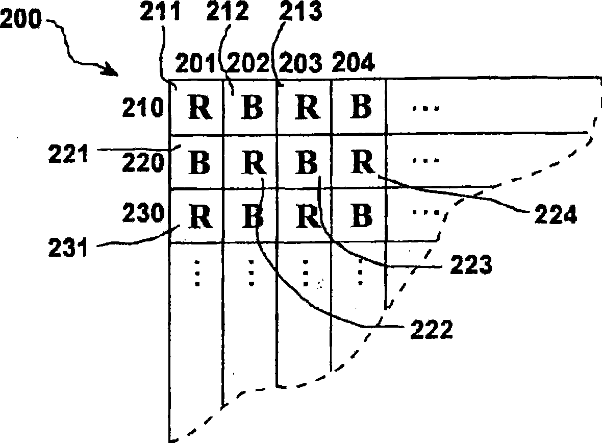
[0047] Figure 2a A section of the second image sensor 200 is schematically shown. The image sensor 200 has pixels R and B of different spectral sensi...


PUM


Abstract

The present invention relates to a method for spatial-frequency filtering with an imaging apparatus (3) having a lens (10), which projects a captured image onto one or several optoelectronic image sensors (100; 200; 41, 42) with photo-sensitive pixels (111, 112, 113, ; 211, 212, 213, ), wherein at least one optoelectronic image sensor (100; 200; 41, 42) and the image projected on it during imaging can be moved relative to each other in the pixel plane, wherein the location vector of this relative movement assumes predetermined locations with a respective predetermined duration.

Description

technical field [0001] The invention relates to a method for spatial frequency filtering and to an image recording device according to the preambles of the independent claims. [0002] The following is basically about movie cameras, but the invention is not limited thereto. It goes without saying that the method according to the invention can likewise be applied to cameras or other image recording devices, for example. Background technique [0003] In order to be able to record images that are as realistic and artifact-free as possible, the camera is designed with an electro-optical image sensor with a regular pixel arrangement, optical prefiltering or spatial frequency filtering. In principle, optical pre-filtering is necessary in image sensors if overlapping (alias) effects are to be avoided. So-called overlapping structures cannot be subsequently removed, for example by means of digital filtering of the pixel data, since digital data cannot distinguish overlapping struc...

Claims


Application Information

Patent Timeline
Patent Type & Authority Applications(China)
IPC IPC(8): G03B5/00H04N5/225H04N5/335
CPCG03B5/00H04N5/2259H04N3/1587G03B2205/0038H04N23/55H04N23/58H04N25/48
Inventor 格尔德·斯图克勒
Owner 格尔德·斯图克勒
Why Eureka
Try Eureka