Automatic door closer structure

A technology of automatic door closing and housing, which is applied in the field of door closers, and can solve the problems of unsmooth operation, inconvenience, intermittent contact between gears and racks, etc.

Inactive Publication Date: 2009-06-17
TAIWAN FU HSING INDAL
View PDF1 Cites 6 Cited by
  • Summary
  • Abstract
  • Description
  • Claims
  • Application Information

AI Technical Summary

Problems solved by technology

[0002] The door closer is mainly used to provide a damping effect on the door panel, so that the door panel has a cushioning effect when it is closed, and the elastic element installed inside the door closer can store energy when compressed, and when the external force is removed from the door panel, it can automatically slow down. The sliding door panel is restored and closed. For example, Taiwan Patent No. 428658 discloses a door closer that uses gears, racks and springs to realize the action of the door closer. However, the gear and the rack of the door closer have backlash when meshing. Existence, under long-term use, the backlash will increase due to wear and tear, causing intermittent contact between the gear and the rack, resulting in unsmooth operation of the door closer
[0003] It can be seen that the above-mentioned existing door closer obviously still has inconvenience and defects in structure and use, and needs to be further improved urgently.
In order to solve the above-mentioned problems, the relevant manufacturers have tried their best to find a solution, but for a long time no suitable design has been developed, and the general product has no suitable structure to solve the above-mentioned problems. This is obviously the relevant industry. Urgent problem

Method used


Image

  • Automatic door closer structure
  • Automatic door closer structure
  • Automatic door closer structure

Examples


Embodiment Construction

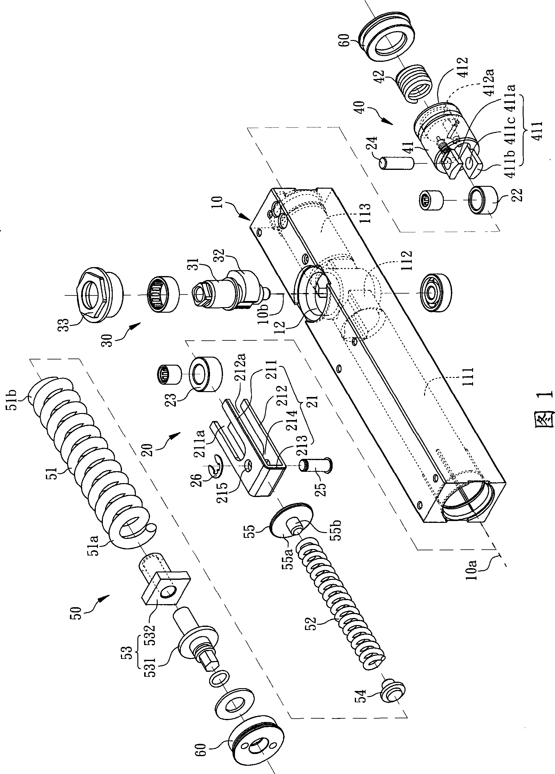
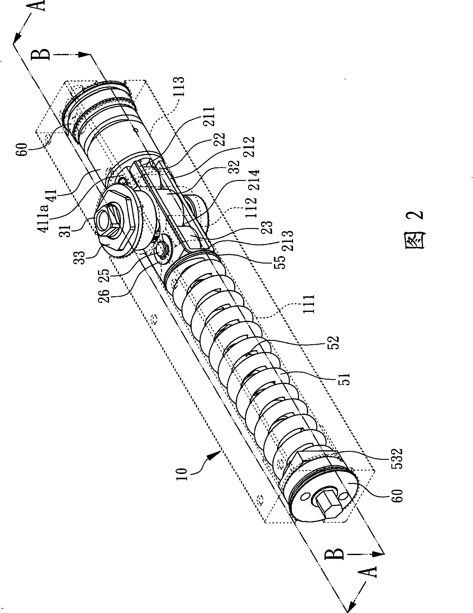
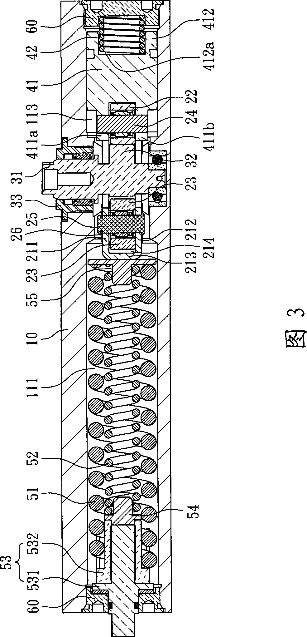
[0055] In order to further explain the technical means and effects of the present invention to achieve the intended purpose of the invention, the specific implementation, structure, features and effects of the automatic door closer structure proposed according to the present invention will be described below in conjunction with the accompanying drawings and preferred embodiments. , will be clearly presented in the following detailed description of preferred embodiments with reference to the drawings. For convenience of description, in the following embodiments, the same elements are denoted by the same numbers.

[0056] Through the description of the specific implementation mode, when the technical means and functions adopted by the present invention to achieve the predetermined purpose can be obtained a deeper and more specific understanding, but the accompanying drawings are only for reference and description, and are not used to explain the present invention be restricted. ...


PUM


Abstract

The invention relates to an automatic door closer structure, which comprises a shell, a sliding set, a transmission set, a piston set and an elastic component. The sliding set is arranged and can move in the middle cavity of the shell, comprising a sliding base, a first trolley wheel and a second trolley wheel, the sliding base is provided with an upper board, a lower board and a slot formed between the upper board and the lower board, the first trolley wheel is arranged and can move in the slot, the second trolley wheel is fixedly arranged in the slot; the transmission set comprises a transmission shaft and an offset cam combined with the transmission shaft, the transmission shaft is hinged in a shaft hole of the shell and penetrates the sliding base, the offset cam is positioned in the slot of the sliding base and is butt connected with the first trolley wheel and the second trolley wheel; the piston set is arranged and can move in the back cavity of the shell, the piston set comprises at least a trunk piston which is provided with a first end part connected with the first trolley wheel; the elastic component is arranged in the front cavity of the shell and is butt connected with the sliding base. The automatic door closer structure provided by the invention can improve the smoothness of the operation.

Description

technical field [0001] The invention relates to a door closer, in particular to an automatic door closer structure which can improve smooth operation. Background technique [0002] The door closer is mainly used to provide a damping effect on the door panel, so that the door panel has a cushioning effect when it is closed, and the elastic element installed inside the door closer can store energy when compressed, and when the external force is removed from the door panel, it can automatically slow down. The sliding door panel is restored and closed. For example, Taiwan Patent No. 428658 discloses a door closer that uses gears, racks and springs to realize the action of the door closer. However, the gear and the rack of the door closer have backlash when meshing. Existence, under long-term use, the backlash will increase due to wear and tear, causing intermittent contact between the gear and the rack, resulting in unsmooth operation of the door closer. [0003] This shows tha...

Claims


Application Information

Patent Timeline
Patent Type & Authority Applications(China)
IPC IPC(8): E05F3/10
Inventor 余勇信
Owner TAIWAN FU HSING INDAL
Why Eureka
Try Eureka