Squitter pulse welding method
A pulse welding and welding torque technology, applied in welding equipment, arc welding equipment, manufacturing tools, etc., can solve problems such as increased line energy and burn-through of base metal, and achieve the effect of suppressing line energy and improving aesthetics.
- Summary
- Abstract
- Description
- Claims
- Application Information
AI Technical Summary
Problems solved by technology
Method used
Image

Examples
Embodiment approach 1
[0126] Hereinafter, embodiments of the invention will be described based on examples with reference to the drawings.
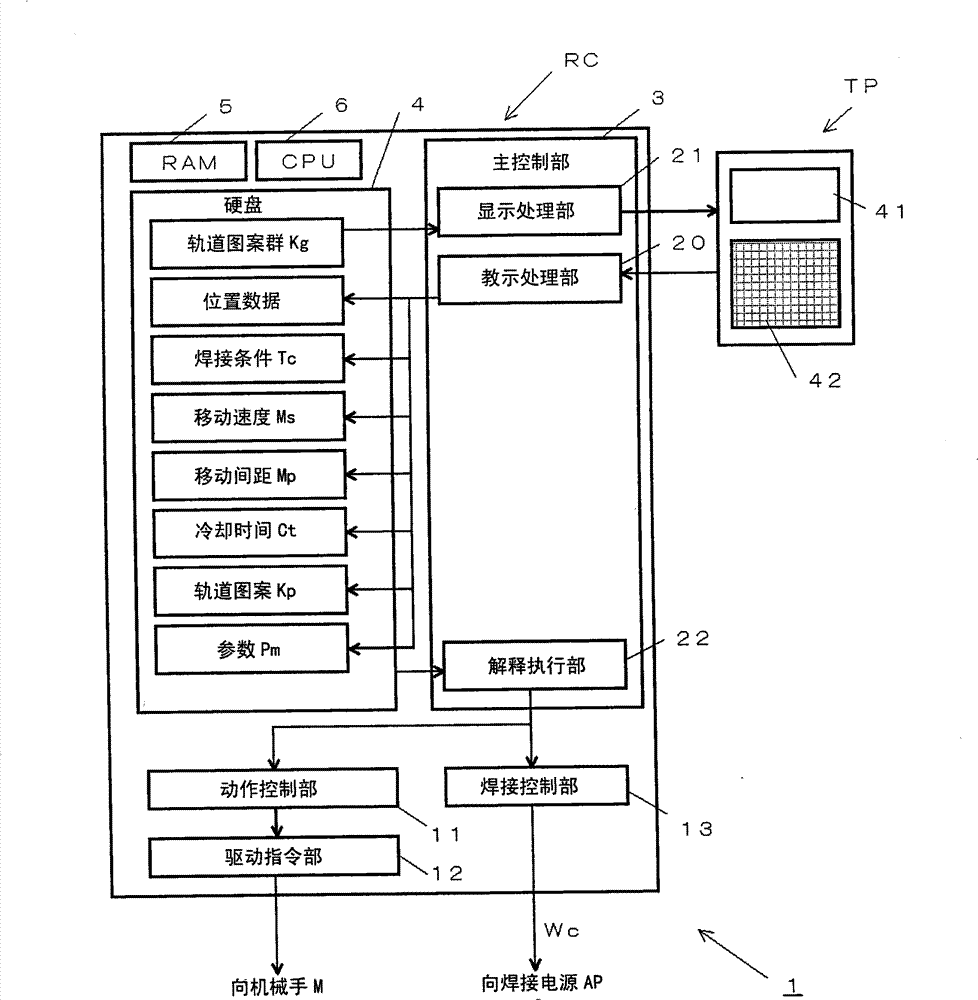
[0127] figure 1 It is a block diagram of the intermittent pulse welding device 1 applicable to the intermittent pulse welding method related to the present invention. In this figure, with the prior art Figure 13 The difference lies in the robot controller RC and the teach pendant TP as the operating unit. Other manipulator M, welding power source AP, welding wire spool 56, gas cylinder 58 and the like that have been described in the prior art are not shown and are omitted. Hereinafter, the robot controller RC and the teach pendant TP constituting the main parts of the present invention will be described.
[0128] The robot control device RC is used to control the welding operation of the robot arm M, and includes: a main control unit 3 serving as the center; and an operation control unit that performs trajectory calculation of the robot arm M, etc., and ou...
Embodiment approach 2
[0160] Next, Embodiment 2 of the present invention will be described. In Embodiment 1, the welding trajectory is generated on the working line direction side of the working position Pn, but in the second embodiment, the welding trajectory is generated around the working position Pn.
[0161] Figure 6 It is a diagram showing how a circular welding track is generated around the working position Pn in the second embodiment. In this figure, with Figure 4 The difference is that the working position Pn is taken as the center position Cc' of the circular welding track Kc'. Others are the same as those in Embodiment 1, and thus description thereof will be omitted.
[0162] The circular welding track Kc' is generated as follows. First, with the work position Pn as the center position Cc', a circular orbit having a circle radius value Cr in the YZ plane is calculated. Then, on the circular orbit, the welding start and end position Wp' is calculated at a position separated from th...
Embodiment approach 3
[0178] Next, Embodiment 3 of the present invention will be described. In Embodiments 1 and 2, the circular welding trajectory Kc (Kc') or the elliptical welding trajectory Kd (Kd') is generated on the side of the working line direction of the working position Pn or around the working position Pn, but in the third embodiment, the generation from The work position Pn faces the spiral welding rail which spirally rotates outward.
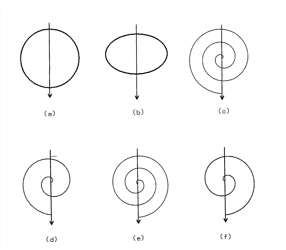
[0179] Figure 9 It is a figure for explaining a spiral welding track. This figure is a view of the YZ plane of the welding line coordinate system described in Embodiment 1 viewed from the X+ direction, and shows how the spiral welding trajectory Kr is drawn on the YZ plane. In this figure, the working position Pn, the working line L, the working line direction Dr and the rotation direction Rd are related to Figure 4 The parts assigned the same symbols are the same, so descriptions are omitted.
[0180] The spiral welding track Kr shown in the figu...
PUM
 Abstract
Description
Claims
Application Information
 - R&D Engineer
- R&D Manager
- IP Professional
- Industry Leading Data Capabilities
- Powerful AI technology
- Patent DNA Extraction
Browse by: Latest US Patents, China's latest patents, Technical Efficacy Thesaurus, Application Domain, Technology Topic.
© 2024 PatSnap. All rights reserved.Legal|Privacy policy|Modern Slavery Act Transparency Statement|Sitemap