Supercharge Your Innovation With Domain-Expert AI Agents!

Optical pickup device and photodetector

An optical pickup device and photodetector technology, which is applied to optical detectors, beam guiding devices, instruments, etc., can solve the problem of inability to use a single-chip dual-wavelength semiconductor laser device, etc., and achieve the effect of stable addressing error detection.

Inactive Publication Date: 2009-07-01
PANASONIC CORP
View PDF2 Cites 0 Cited by
  • Summary
  • Abstract
  • Description
  • Claims
  • Application Information

AI Technical Summary

Problems solved by technology

Therefore, it is impossible to configure an inexpensive optical system using a monolithic dual-wavelength semiconductor laser device arranged close to two light sources

Method used


Image

  • Optical pickup device and photodetector
  • Optical pickup device and photodetector
  • Optical pickup device and photodetector

Examples


Embodiment Construction

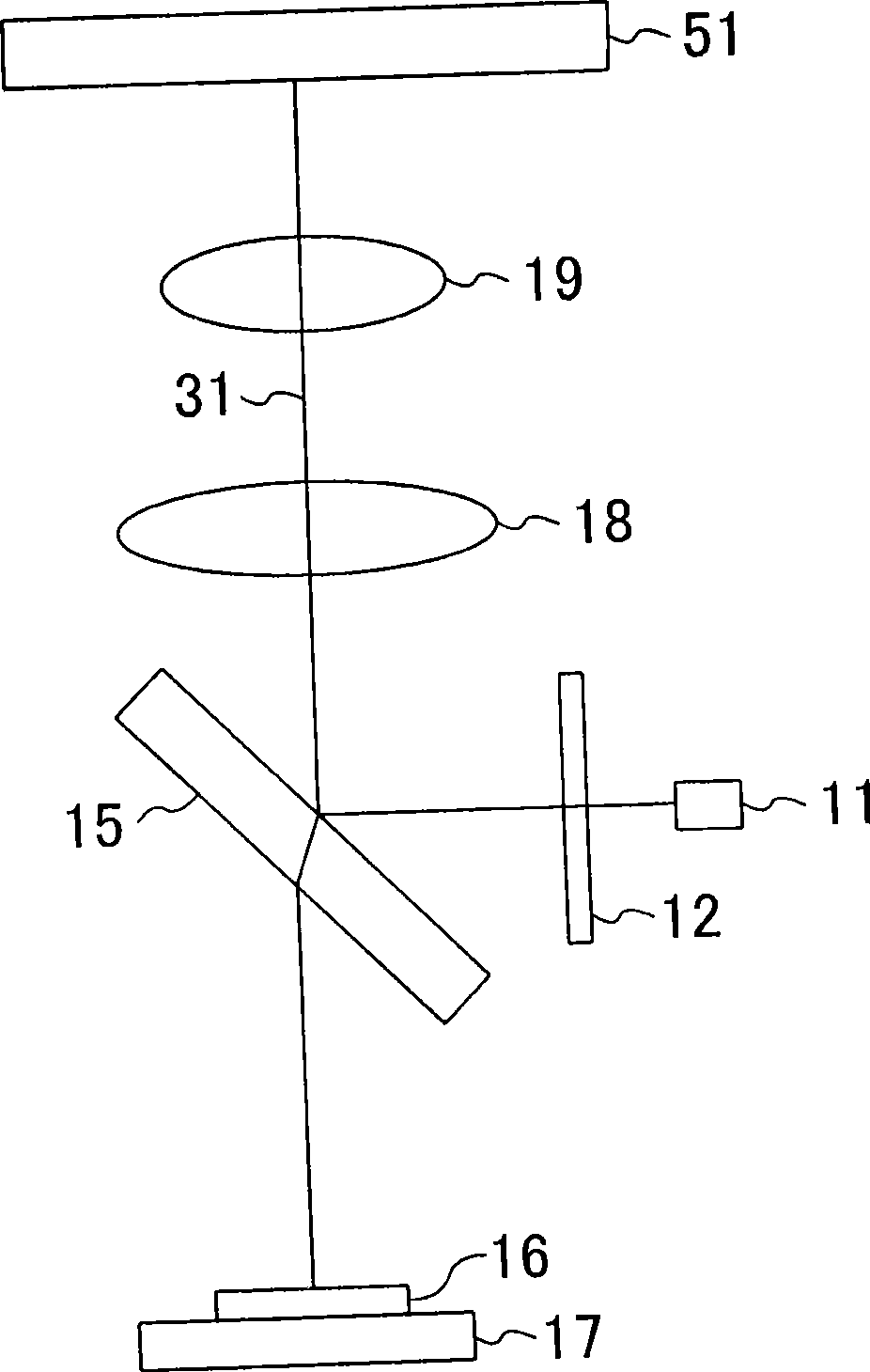
[0049] One embodiment of the present invention will be described with reference to the drawings. figure 1 A schematic configuration of the optical pickup device according to the embodiment is shown.

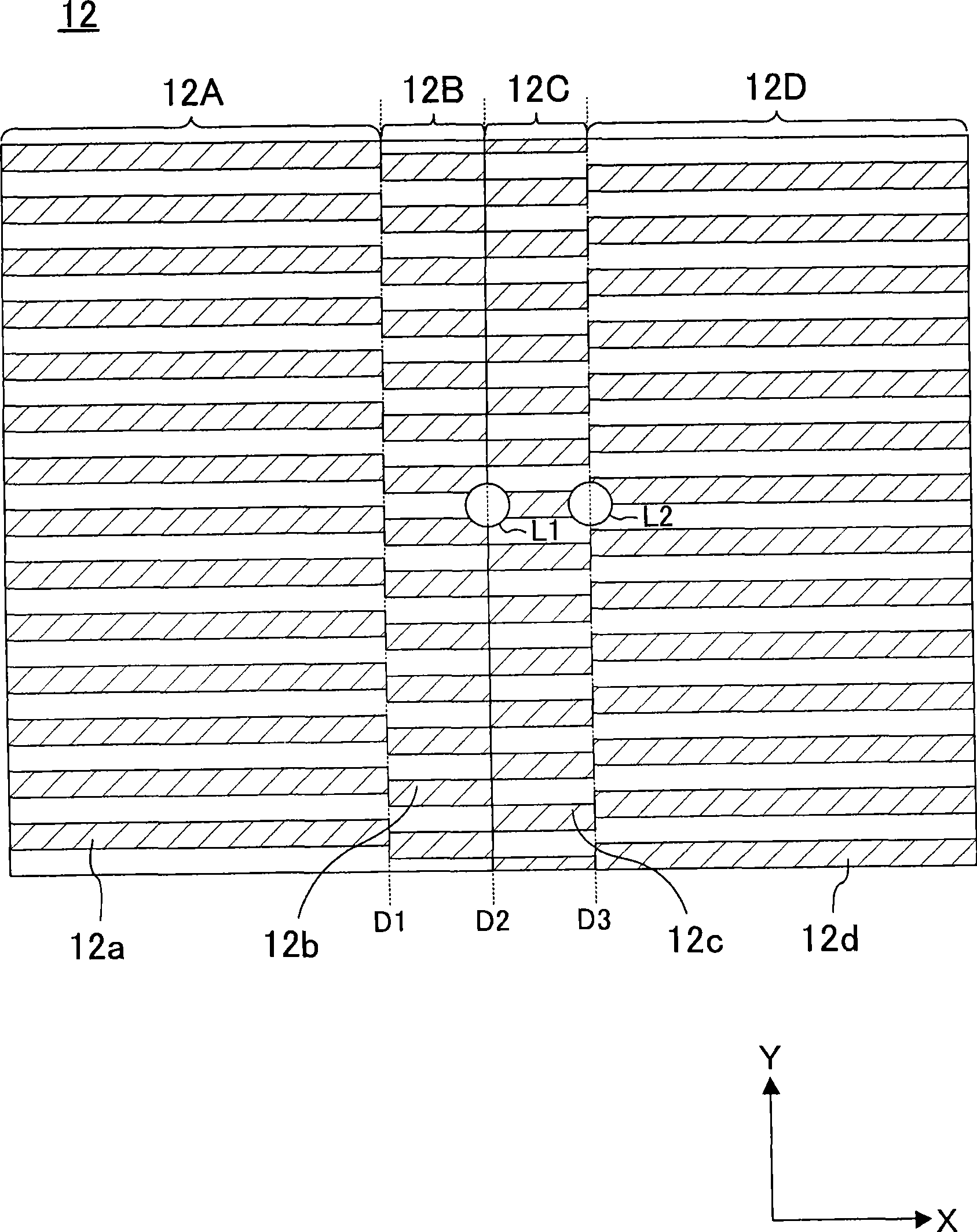
[0050] Such as figure 1 As shown, the optical pick-up device of the present embodiment has a light source 11, which emits a light beam 31 with a wavelength of λ1 for recording information on an optical information recording medium 51 and reproducing the information recorded on the optical information recording medium 51. A monolithic dual-wavelength semiconductor laser element for a light beam 32 with a wavelength of λ2, and the like. In addition, the optical pick-up device of the present embodiment is equipped with: a diffraction grating 12, which diffracts and splits the light beam 31 to at least form the main beam 31a of the 0th order diffracted light, the sub-beam 31b of the +1st order diffracted light, and the sub-beam 31b of the −1st order diffracted light. Light beam 3...


PUM


Abstract

An optical pickup device includes: a first light-receiving element for receiving a main beam of a first light beam; second and third light-receiving elements for receiving sub-beams of the first light beam; a fourth light-receiving element for receiving a main beam of a second light beam; and fifth and sixth light-receiving elements for receiving sub-beams of the second light beam. The first through third light-receiving elements are located on a first line with the first light-receiving element sandwiched between the second and third light-receiving elements. The fourth through sixth light-receiving elements are located on a second line with the fourth light-receiving element sandwiched between the fifth and sixth light-receiving elements. The first line and the second line are parallel to each other.

Description

technical field [0001] The present invention relates to an optical pickup device and a photodetector of an optical information processing device for recording information on an optical information recording medium and reproducing or deleting information recorded on the optical information recording medium. Background technique [0002] Optical information recording media (optical discs) such as CD (Compact Disc) and DVD (Digital Versatile Disc) use an objective lens to condense light beams emitted from a light source such as a semiconductor laser device on the recording track (track) of the optical disc, and use a photodetector to detect The reflected light of the optical disc is converted into electrical signals for recording and reading. For a high-speed rotating optical disc, in order to accurately focus the beam on the desired recording track, it is necessary to detect the focus error signal and the tracking error signal, and combine the disc surface shake and eccentrici...

Claims


Application Information

Patent Timeline
Patent Type & Authority Applications(China)
IPC IPC(8): G11B7/135G11B7/09G11B7/13
CPCG11B7/094G11B7/0903G11B7/0943G11B7/131G11B7/1275G11B7/1353
Inventor 山本博昭岛田直人中西直树奥田拓也白川泰史
Owner PANASONIC CORP
Features
  • R&D
  • Intellectual Property
  • Life Sciences
  • Materials
  • Tech Scout
  • Unparalleled Data Quality
  • Higher Quality Content
  • 60% Fewer Hallucinations
Learn More