
Slim type optical disc drive

a slim-type, optical disc technology, applied in the direction of record information storage, record carrier construction details, instruments, etc., can solve the problems of limited slimming of conventional optical disc drives, difficult to maintain a gap between disc d and the tray, and heavy and complicated trays

Inactive Publication Date: 2005-06-21
SAMSUNG ELECTRONICS CO LTD
View PDF10 Cites 42 Cited by
  • Summary
  • Abstract
  • Description
  • Claims
  • Application Information

AI Technical Summary

Benefits of technology

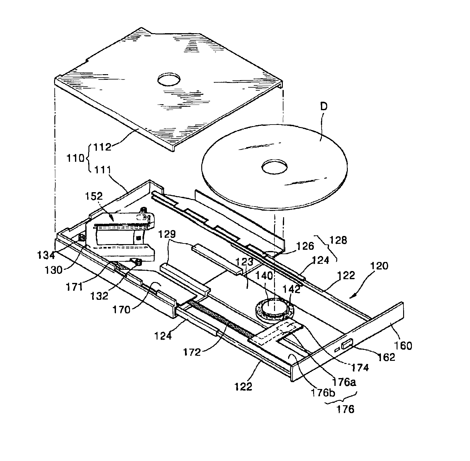
[0014]To solve the above and other problems, it is an object of the present invention to provide a slim type optical disc drive in which only a spindle motor is installed on a tray, while an optical pickup unit and a pickup transport are disposed in a housing, so that the overall construction of the optical disc drive is simplified, the tray can be more easily carried, and a disc can be more easily loaded and unloaded.

Problems solved by technology

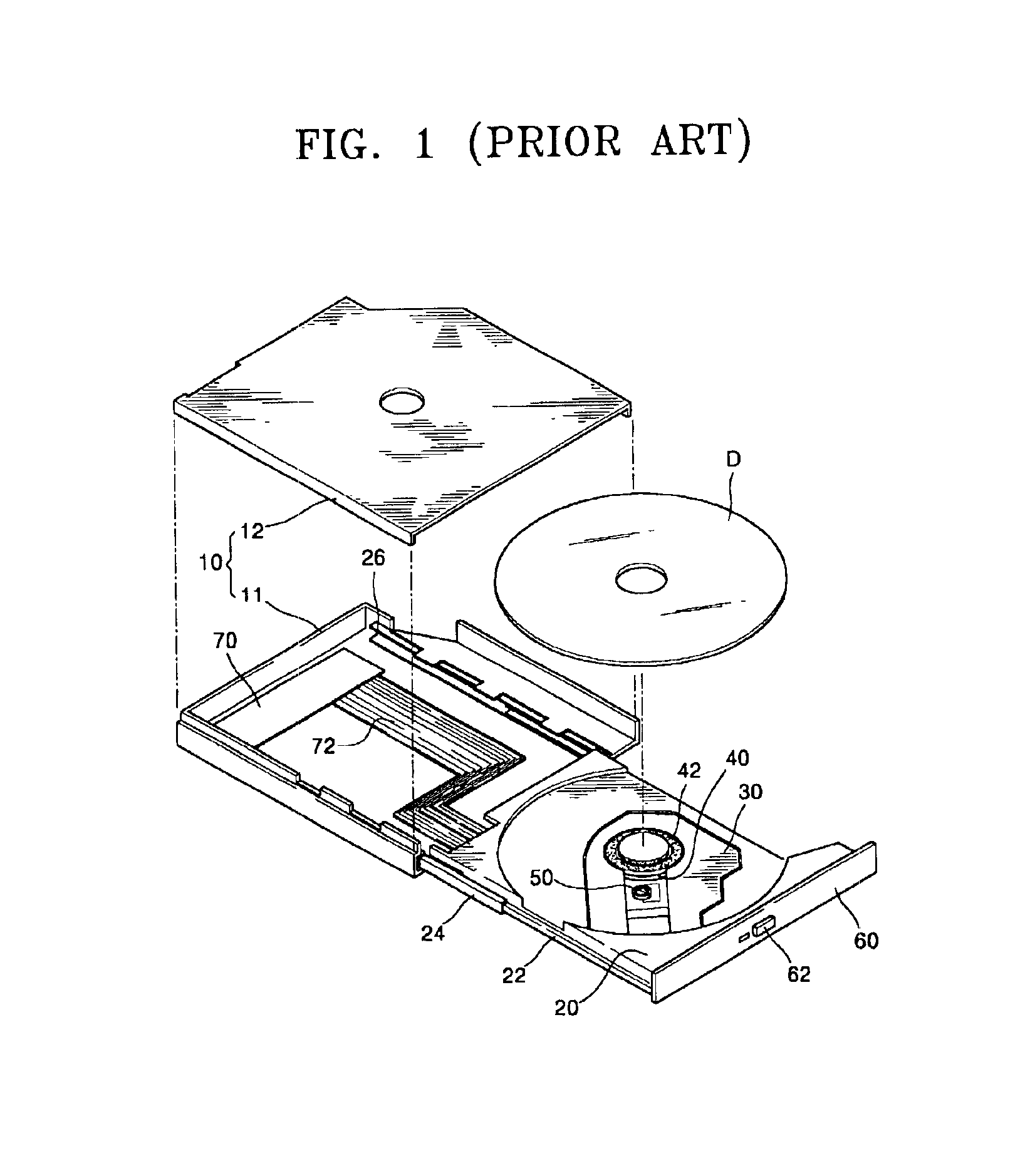
However, in the conventional slim type optical disc drive, the spindle motor 40, the optical pickup unit 50, and the pickup transport are all installed in the tray 20, making the tray 20 heavy and complicated as well as thick.
Therefore, there are limits to slimming the conventional optical disc drive.
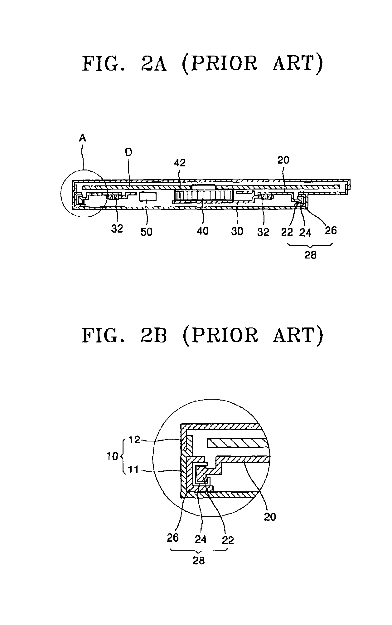
Further, when designing the complicated construction described above, it is difficult to maintain a gap between the disc D and the tray 20, which is necessary to prevent the disc D from contacting the tray 20 due to vibrations.
Moreover, when attempting to reduce a vibration of the spindle motor 40, which is the main source of the vibrations, it is difficult to find the vibration transmission path in the tray 20, which further complicates the design for reducing the vibrations.

Method used


Image

  • Slim type optical disc drive
  • Slim type optical disc drive
  • Slim type optical disc drive

Examples


Embodiment Construction

[0040]Hereinafter, embodiments of the present invention will be described with reference to the accompanying drawings, examples of which are illustrated in the accompanying drawings, wherein like reference numerals refer to the like elements throughout. The embodiments are described below in order to explain the present invention by referring to the figures.

[0041]FIG. 3 is an exploded perspective view illustrating the construction of a slim type optical disc drive according to an embodiment of the present invention. FIG. 4A is a vertical transverse section schematically illustrating the slim type optical disc drive of FIG. 3 in which a disc is loaded, and FIG. 4B is an enlarged view of the part B of FIG. 4A. Referring to FIGS. 3 through 4B, the slim type optical disc drive includes a housing 110 having a lower case 111 and an upper case 112, and a tray 120 that slides in and out of the housing 110. A main base 130 is located on the lower case 111 in the housing 110, at the rear port...


PUM

PropertyMeasurementUnit
heightaaaaaaaaaa
heightaaaaaaaaaa
flexibleaaaaaaaaaa

Abstract

In a slim type optical disc drive, an optical pickup unit and an optical pickup transport assembly are installed on a main base disposed in a housing having a lower case and an upper case. A spindle motor is mounted on a tray so as to slide in and out of the housing. A spindle motor printed circuit board is mounted on the tray, and a main printed circuit board is fixed to the lower case. A flexible printed circuit connects the spindle motor and main printed circuits boards. The tray includes a table which supports the spindle motor, and side frame bars located at sides of the tray and spaced apart from the table. A pair of guide ribs are arranged in the housing to guide the movement of the table. In the slim type optical disc drive, only the spindle motor is disposed on the tray.

Description

CROSS-REFERENCE TO RELATED APPLICATION[0001]This application claims the benefit of Korean Application No. 2001-69500, filed Nov. 8, 2001 in the Korean Intellectual Property Office, the disclosure of which is incorporated herein by reference.BACKGROUND OF THE INVENTION[0002]1. Field of the Invention[0003]The present invention relates to an optical disc drive, and more particularly, to a slim type optical disc drive that has a simple construction, and allows a tray to be more easily carried and a disc to be more easily loaded and unloaded.[0004]2. Description of the Related Art[0005]As is generally known in the art, an optical disc drive records and reproduces information using light incident on a recording medium such as a compact disc (CD) or a digital versatile disc (DVD). Optical disc drives are generally used in computers and especially in notebook computers, a slim type optical disc drive of very small thickness is used.[0006]FIG. 1 is an exploded perspective view schematically ...

Claims


Application Information

Patent Timeline
Patent Type & Authority Patents(United States)
IPC IPC(8): G11B17/04G11B33/08G11B17/056G11B25/04G11B33/12
CPCG11B17/056G11B17/04
Inventor PARK, DAE-KYONGSUNG, BU-HYUNJANG, DONG-SEOBJUN, GYU-CHAN
Owner SAMSUNG ELECTRONICS CO LTD
Learn More