Optical disk apparatus

a technology of optical disks and optical disks, applied in the direction of digital recording/reproducing, digital signal error detection/correction, data recording, etc., can solve the problems of inability to conduct servos to the track center, inability to obtain sufficient correction effects, and deviation and offset, etc., to achieve low-precision, low-cost, fine frequency characteristics

Inactive Publication Date: 2011-03-17
HITACHI MEDIA ELECTORONICS CO LTD
View PDF3 Cites 41 Cited by
  • Summary
  • Abstract
  • Description
  • Claims
  • Application Information

AI Technical Summary

Benefits of technology

[0004]An important factor for reliability of the optical disk apparatuses is the stability of the tracking servo control. A main factor determining the stability of the tracking servo control is the signal stability that a zero point of the tracking error signals agrees with a center of a recording information track correctly under various use conditions. A deviation from the zero point is called offset of the tracking error signal.
[0007]The present invention has been made in order to solve the problem. An object of the present invention is to provide an optical disk apparatus in which the offset of the tracking error signal is corrected by signal processing at low cost certainly.
[0009]In the optical disk apparatus according to the present invention, double correction effects are obtained fast by a combination of correction among pickup output signals and circuit side correction. Therefore, low-precision low-cost corrector can be used for the circuit side correction, and fine frequency characteristics are obtained.

Problems solved by technology

However, a deviation and an offset are caused by a manufacturing variation of a pickup, which is an optical head, or deviation of a medium such as a warp or undulation.
Since the zero point of the signal deviates, it becomes impossible to conduct servo to the track center correctly and it becomes a cause of run off during the recording and reproduction of the disk.
However, there is a problem that a sufficient correction effect cannot be obtained due to an influence of vibration characteristics of the object lens actuator itself and the cost of the corrector becomes high.

Method used


Image

  • Optical disk apparatus
  • Optical disk apparatus
  • Optical disk apparatus

Examples


Embodiment Construction

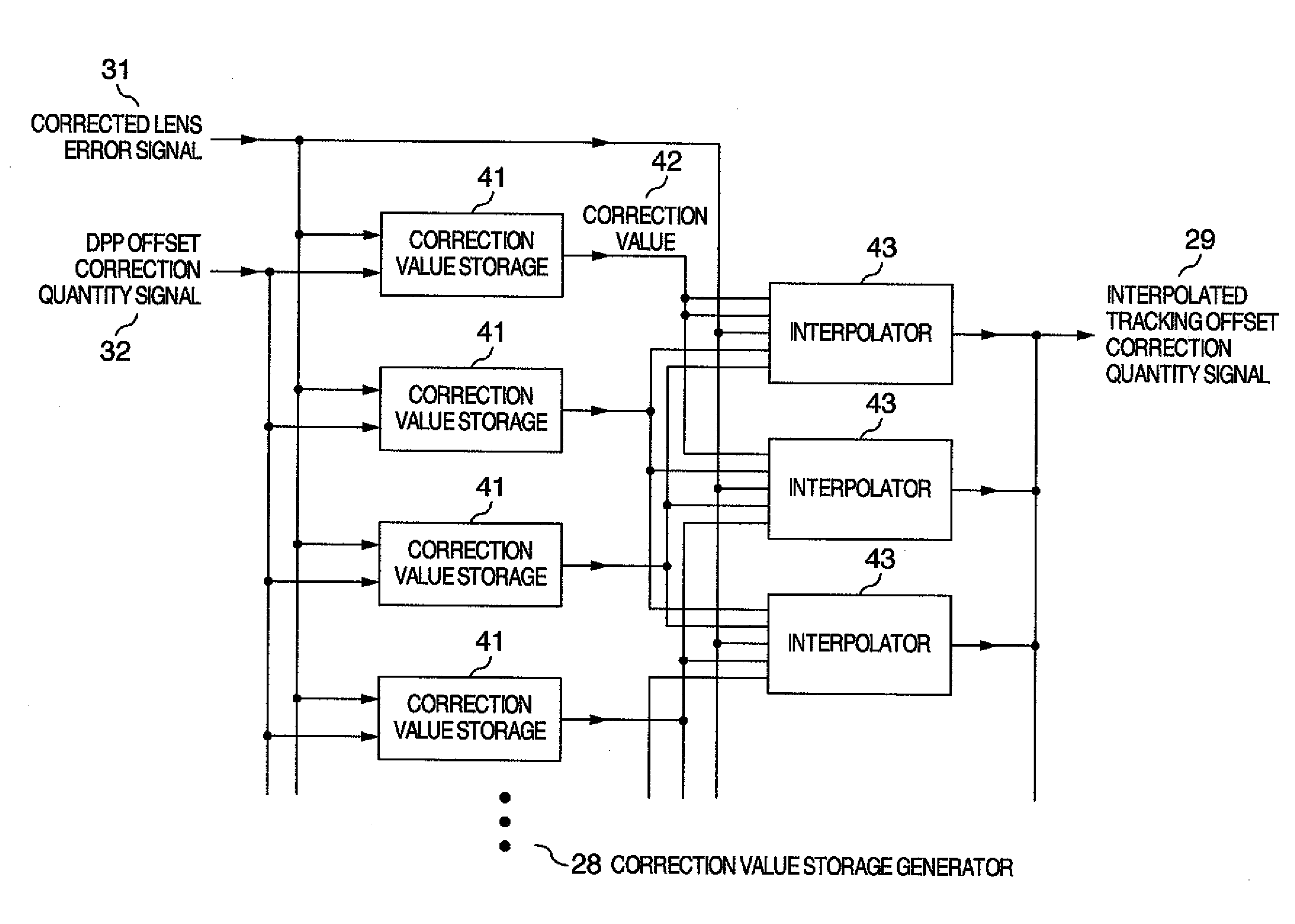
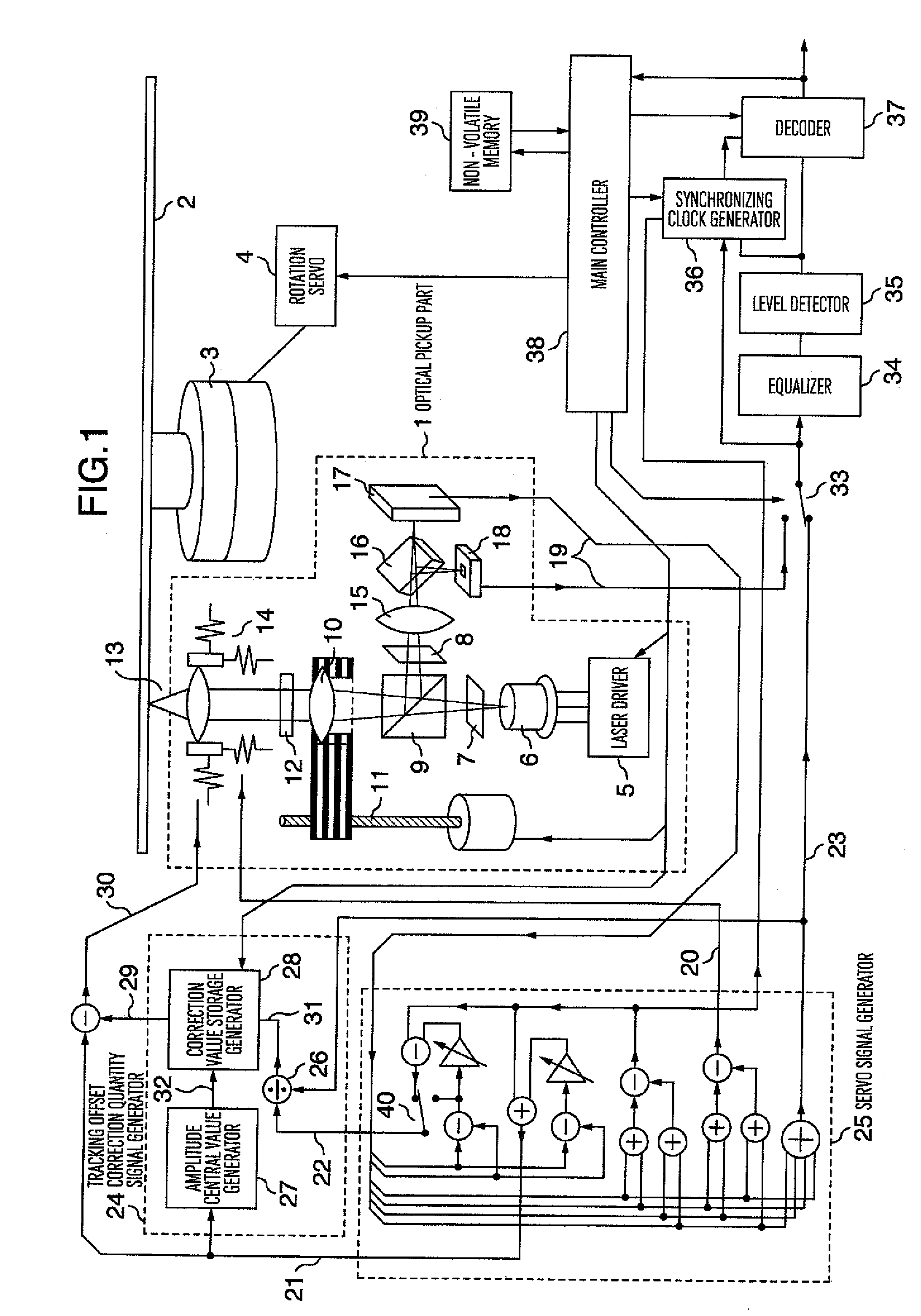
[0018]Hereafter, an optical disk apparatus according to the present invention will be described. One of features of the optical disk apparatus according to the present invention is that the offset of the tracking error signal can be corrected simply and certainly on the circuit side according to learning information on the LSI side which is as little as several tens bytes by making the most of characteristics of the pickup output signal. The optical disk apparatus according to the present invention can be implemented by a combination of an optical pickup having a signal output corresponding to the correction and a signal processor having a correction processing function. Furthermore, a higher function and a higher reliability can be implemented with lower cost by incorporating the signal processor into a single integrated circuit chip having an error correction function.

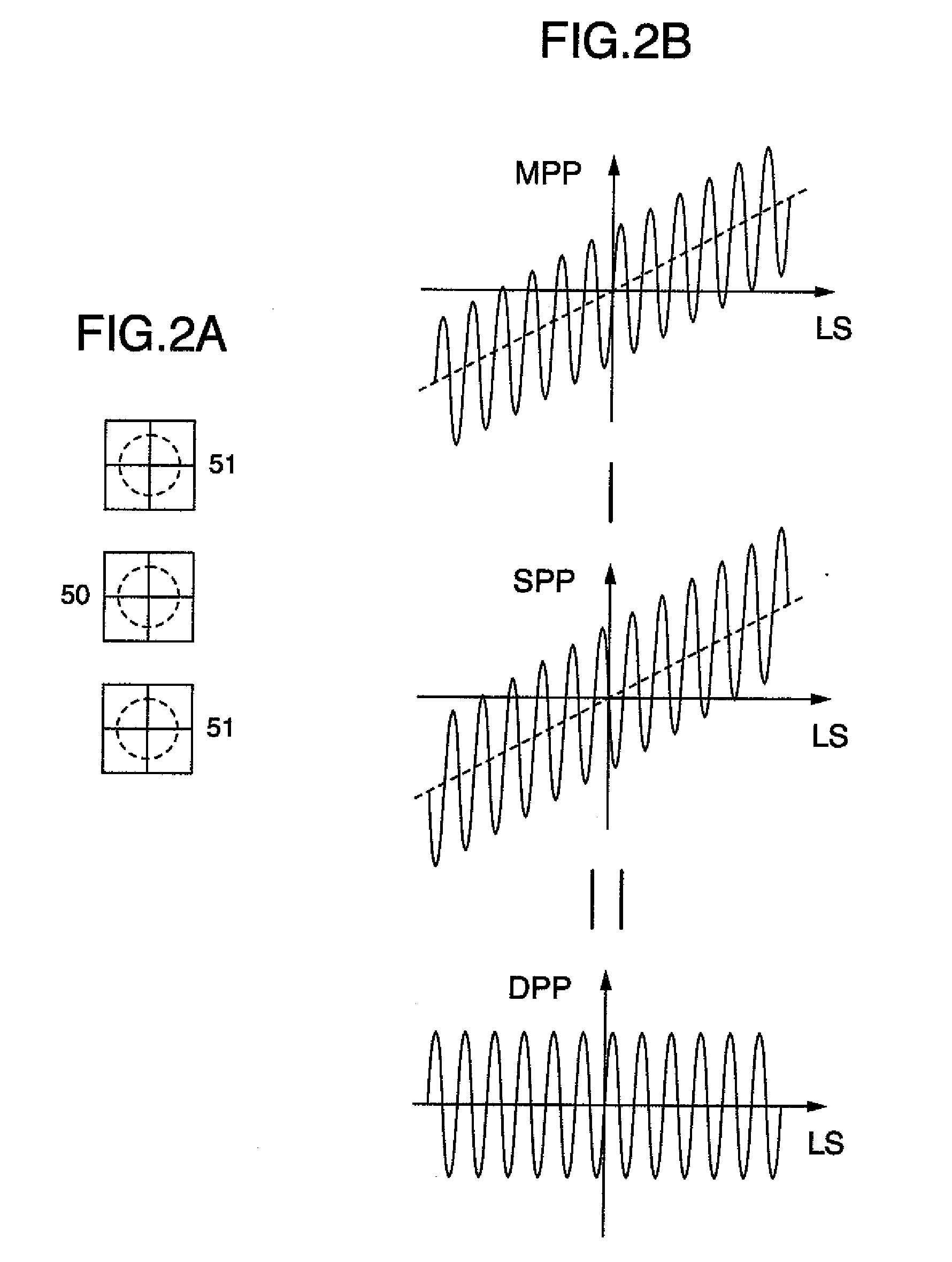
[0019]Hereafter, embodiments of the present invention will be described with reference to FIGS. 1 to 7. For facili...


PUM

PropertyMeasurementUnit
stabilityaaaaaaaaaa
frequencyaaaaaaaaaa
areaaaaaaaaaaa

Abstract

In an optical disk apparatus, an optical pickup includes an actuator for driving an object lens, and a sensed signal output part for making it possible to generate a tracking error signal and a lens error signal by addition / subtraction, and a signal processor includes a servo signal generator for generating a tracking error signal and a lens error signal on the basis of a signal supplied from the sensed signal output part, and a tracking offset correction quantity signal generator supplied with the lens error signal to output a tracking offset correction quantity signal. DC (direct current) offset correction is conducted by conducting addition / subtraction between the tracking error signal and both the lens error signal and the tracking offset correction quantity signal.

Description

INCORPORATION BY REFERENCE[0001]The present application claims priority from Japanese application JP2009-214014 filed on Sep. 16, 2009, the content of which is hereby incorporated by reference into this application.BACKGROUND OF THE INVENTION[0002]The present invention relates to an optical information recording-reproducing apparatus, and in particular to an optical disk apparatus. However, the present invention can be applied to general apparatuses using an optical servo function in which tracking control is exercised by using an optical signal.[0003]As a background art, there is a technique disclosed in JP-A—2006-294189. “PROBLEM TO BE SOLVED” is described in JP-A-2006-294189 to be “to provide a tracking control method of an optical disk device capable of correcting off-set of a tracking error signal with high precision even when there are nonlinear characteristics e.g. wherein a shift amount of a position of an objective lens to a mechanically neutral position of the objective le...

Claims


Application Information

Patent Timeline
Patent Type & Authority Applications(United States)
IPC IPC(8): G11B20/18
CPCG11B7/0901G11B2007/0013G11B7/094G11B7/0903
Inventor ISSHIKI, FUMIOMARUYAMA, HIDEKI
Owner HITACHI MEDIA ELECTORONICS CO LTD
Why Eureka
Try Eureka