
Modularized switch and operating method thereof

A switch and modular technology, applied in the field of modular switches and their operation, can solve the problems of reducing the reliability of the whole switch system, increasing the cost of switches, and complicated wiring, so as to ensure the speed of message exchange, reduce components, and simplify wiring Effect

Active Publication Date: 2011-06-22
BEIJING XINWANG RUIJIE NETWORK TECH CO LTD
View PDF0 Cites 0 Cited by
  • Summary
  • Abstract
  • Description
  • Claims
  • Application Information

AI Technical Summary

Problems solved by technology

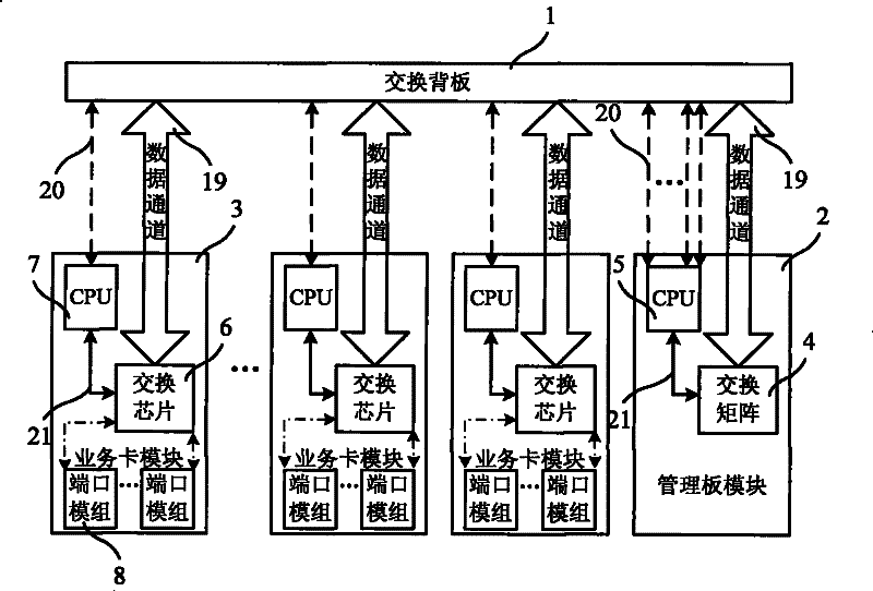
[0004] However, the above technology has certain defects: 1) each service card module needs to be configured with a CPU, which increases the cost of the switch; 2) the management channel is used to realize the configuration management and communication of each service card module by the management board module The 100M Ethernet cable "100Base-T" is often used, which has limited bandwidth and complicated wiring; 3) When using "100Base-T" and other management channels, it is necessary to add a physical layer conversion chip for the management channel for signal conversion, so a switch is added. The cost of the switch, while the increase in the number of components also reduces the reliability of the switch system

Method used


Image

  • Modularized switch and operating method thereof
  • Modularized switch and operating method thereof
  • Modularized switch and operating method thereof

Examples


no. 1 example

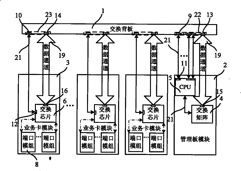
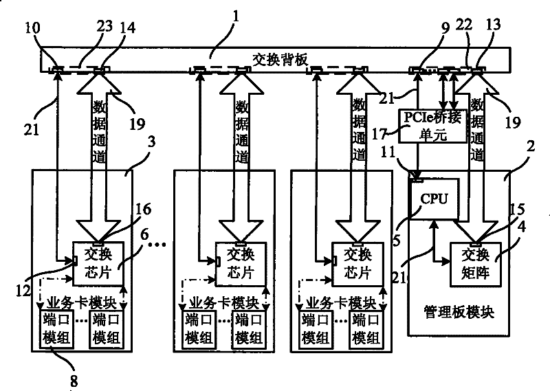
[0030] figure 2 It is a schematic structural diagram of the first embodiment of the modular switch of the present invention. Such as figure 2 As shown, the modular switch in this embodiment includes: a switching backplane 1, and a management board interface set 22 arranged on the switching backplane 1 for plugging in the management board module 2 and a set of management board interfaces for plugging in the service card module 3. Business card interface set 23. Generally, there is one management board interface set 22 for connecting one management board module 2 , and there are usually multiple service card interface sets 23 for connecting multiple service card modules 3 . Specifically, the management board interface set 22 includes a first data channel interface 13 and a first PCIe interface 9; the first data channel interface 13 is used to connect the switch matrix 4 in the management board module 2 to exchange messages; the first PCIe interface 9 It is used to connect t...


PUM


Abstract

The present invention relates to a modularized switchboard and an operating method thereof. The management board interface set of the switchboard comprises a first data channel interface and a first PCIe interface. The first data channel interface is used for connecting the switching matrices in the management board module. The first PCIe interface is used for connecting with a central processor in the management board module for receiving management information. The service card interface set comprises a second data channel interface and a second PCIe interface. The second data channel interface is used for connecting the switching chip in the service card interface. The second PCIe interface is connected with the first PCIe interface for receiving the management information transmitted by the central processor in the management board module. Furthermore the second PCIe interface is used for connecting with the switching chip in the service card module and transmitting management information for controlling the switching chip. The PCIe circuit between the first PCIe interface and the second PCIe interface is laid on the switching backboard. The technical solution of the inventioncan simplify the structure and reduce the cost.

Description

technical field [0001] The present invention relates to modular switch technology, in particular to a modular switch and its operating method. Background technique [0002] The switch is a device for exchanging a large amount of message data. In order to meet the different application requirements of users, the existing technology modularizes the Ethernet interface to form a service card module. Users can choose different service card modules to meet different application environments and increase the number of users. The use of ports, this switch is called a modular switch. [0003] figure 1 It is a structural schematic diagram of a modular switch in the prior art. Such as figure 1 As shown, the modular switch at least includes a switch backplane 1 , a management board module 2 and a service card module 3 . The switch backplane 1 is used to set various lines and plug ports, and the management board module 2 and the service card module 3 are plugged into the switch backp...

Claims


Application Information

Patent Timeline
Patent Type & Authority Patents(China)
IPC IPC(8): H04L12/02H04L12/56H04L12/931
Inventor 林健
Owner BEIJING XINWANG RUIJIE NETWORK TECH CO LTD
Learn More