Method and apparatus for temperature sensing in integrated circuits

a temperature sensor and integrated circuit technology, applied in the field of electronic systems, can solve the problems of inability to determine the placement of temperature sensors, inability to generate heat evenly, and inability to achieve uniform heat generation, etc., and achieve the effect of reducing area and facilitating signal routing

Inactive Publication Date: 2008-11-25
ADVANCED MICRO DEVICES INC
View PDF20 Cites 54 Cited by
  • Summary
  • Abstract
  • Description
  • Claims
  • Application Information

AI Technical Summary

Benefits of technology

[0009]The use of remote temperature sensor circuits based on ring oscillators may allow for area savings and / or allow the use of a greater number of temperature sensors, and may also allow for easier routing of the signal paths since the outputs digital signals. These digital signals may be driven by a core repeater, and do not require shielding.

Problems solved by technology

One of the problems that must be dealt with in the design of electronic systems is the generation of heat.
This is due to the fact that many of these IC's do not generate heat evenly.
Determining the placement of temperature sensors may not always be a straightforward issue.
Circuit density in some areas where temperature sensors are necessary may limit placement options.
Another consideration that may limit the placement of temperature sensors is the routing of signals, particularly in dense areas such as a processor core.
Thus, limits on the number of temperature sensing circuits and the placement of each may in turn reduce the effectiveness of the overall temperature sensing system.
Power supply considerations may be another limiting factor, as power supply voltages most suitable for certain types of sensors (e.g., analog power supplies for analog temperature sensors) may be unavailable in a given processor core.

Method used


Image

  • Method and apparatus for temperature sensing in integrated circuits
  • Method and apparatus for temperature sensing in integrated circuits
  • Method and apparatus for temperature sensing in integrated circuits

Examples


Embodiment Construction

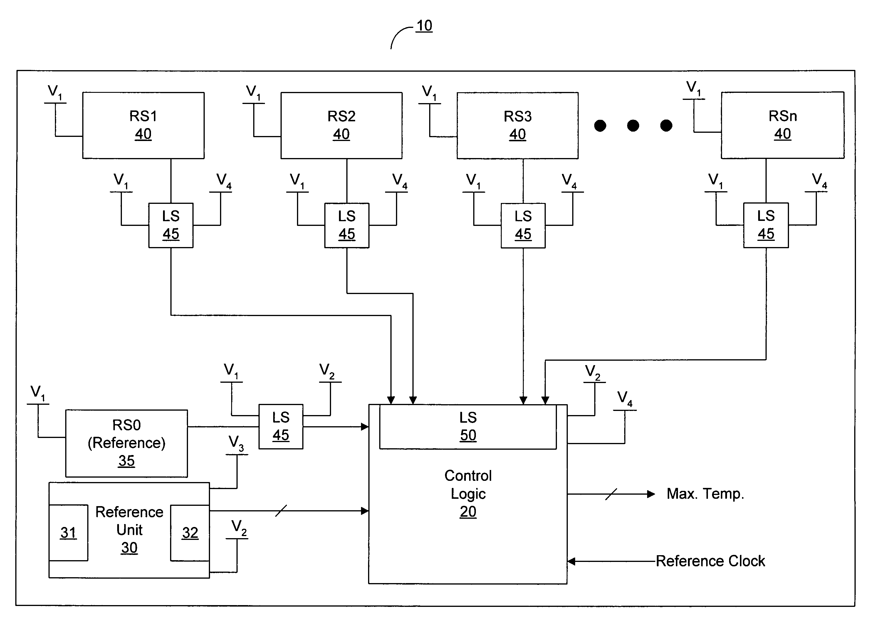
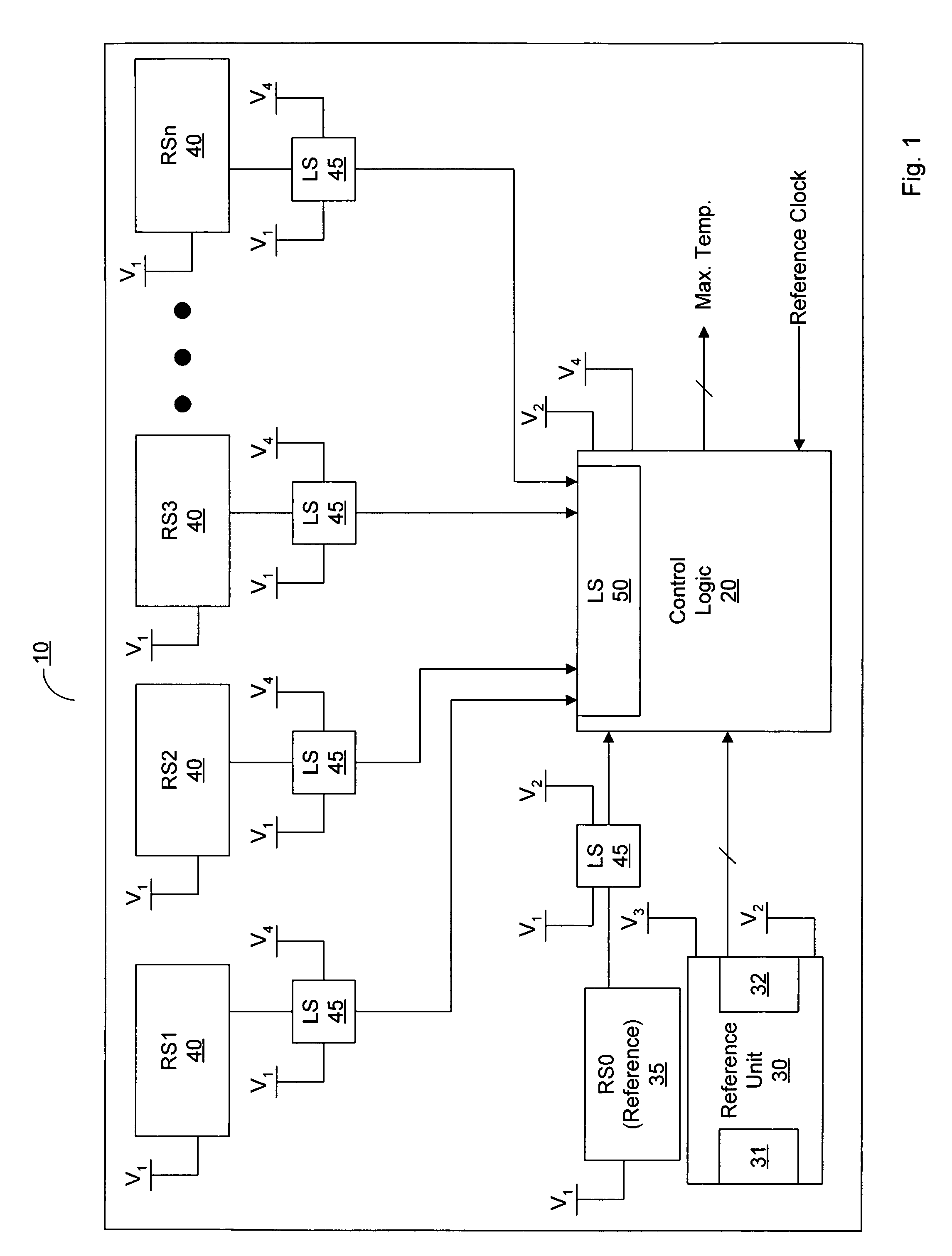
[0016]Turning now to FIG. 1, a block diagram of one embodiment of an integrated circuit having a temperature monitoring system is shown. In the embodiment shown, the circuitry of integrated circuit (IC) 10 includes a control logic unit 20. IC 10 includes a plurality of remote temperature sensors 40, each of which is operatively coupled to control logic unit 20. In this particular embodiment, each of the remote temperature sensors 40 is in a different voltage domain than control logic unit 20. Thus, each remote temperature sensor 40 is coupled to control logic unit 20 via a level shifter. Embodiments wherein the remote temperature sensors 40 are in the same voltage domain as control logic unit 20 (and thus obviating the need for level shifters 45) are possible and contemplated.

[0017]In addition to the plurality of remote temperature sensors 40, a reference sensor 35 and a reference unit 30 are also coupled to control logic unit 20. Reference unit 30 includes a temperature sensor 31, ...


PUM

PropertyMeasurementUnit
frequencyaaaaaaaaaa
frequencyaaaaaaaaaa
voltageaaaaaaaaaa

Abstract

A method and apparatus for temperature sensing in an IC. The IC includes a plurality of remote temperature sensors each coupled to a control logic unit. The plurality of remote temperature sensors may be distributed throughout the integrated circuit. The integrated circuit includes a reference unit coupled to provide a reference temperature to the control logic unit and a reference sensor coupled to provide a signal having a reference frequency to the control logic unit. The reference unit and the reference sensor are located near each other. The control logic unit is configured to correlate the reference frequency received from the reference sensor with the reference temperature received from the reference unit. The control logic unit is further configured to determine the temperature of each of the remote temperature sensors based on this correlation, and also configured to determine the maximum temperature of all of the temperature sensors.

Description

BACKGROUND OF THE INVENTION[0001]1. Field of the Invention[0002]This invention relates to electronic systems, and more particularly, to the detection of temperatures in an integrated circuit.[0003]2. Description of the Related Art[0004]One of the problems that must be dealt with in the design of electronic systems is the generation of heat. Integrated circuits (IC's) are a source of a significant portion of the heat generated by electronic circuits. Thus, many IC's include one or more temperature sensors to allow the monitoring of the temperature of the IC die during operation. Various mechanisms may be used with temperature sensors to reduce or cut off power to an IC when its temperature reaches a critical point that above which damage might occur.[0005]Some IC's may require multiple temperature sensors. This is due to the fact that many of these IC's do not generate heat evenly. Some portions of the silicon die may include a higher circuit density than other areas, and thus may ge...

Claims


Application Information

Patent Timeline
Patent Type & Authority Patents(United States)
IPC IPC(8): G01K3/00
CPCG01K7/203
Inventor LIU, HUININGHEWITT, LARRY D.
Owner ADVANCED MICRO DEVICES INC
Why Eureka
Try Eureka