Input device and process for manufacturing the same, portable electronic apparatus comprising input device

a technology of input device and input device, which is applied in the direction of static indicating device, pulse technique, instruments, etc., can solve the problems of inability to increase the thickness of the spacer unnecessarily, the accuracy the rise of the thickness of the spacer, so as to improve the efficiency of the mounting work of the piezoelectric actuator, the effect of high accuracy

Inactive Publication Date: 2010-04-20
THOMSON LICENSING SA
View PDF24 Cites 53 Cited by
  • Summary
  • Abstract
  • Description
  • Claims
  • Application Information

AI Technical Summary

Benefits of technology

[0018]An object of the present invention is to provide an input apparatus that accomplishes at low cost a force sense feedback function for causing a panel to deform corresponding to an input operation.
[0019]Another object of the present invention is to provide a method for producing an input apparatus that accomplishes at low cost a force sense feedback function for causing a panel to deform corresponding to an input operation.
[0023]In the input apparatus according to the present invention, a piezoelectric actuator contacts the panel except for a part of a flexible wiring board. Since the thickness of the flexible wiring board can be controlled with relatively high accuracy, the accuracy of the mounting position in the thickness direction of the piezoelectric actuator is improved. In addition, the drive force of the piezoelectric actuator is effectively transferred to a spring or the like. Moreover, the piezoelectric actuator is mounted to a pair of through-holes formed in the flexible wiring board. The piezoelectric actuator is mounted so that it contacts the panel except for a part of the flexible wiring board. Thus, the mounting work of the piezoelectric actuator can be effectively performed. When wiring terminals formed at end portions of the piezoelectric actuator and electrodes formed on the flexible wiring board are electrically connected, routing of cables can be easily performed. Thus, according to the present invention, the panel of the input apparatus has a high performance force sense feedback function. The input apparatus can be produced at low cost.
[0026]In a method for producing an input apparatus according to the present invention, an input apparatus having a structure of which a piezoelectric actuator contacts a panel through a part of a flexible wiring board. Since the thickness of the flexible wiring board can be controlled with relatively high accuracy, in this structure, the accuracy of the mounting position in the thickness direction of the piezoelectric actuator is improved. In addition, drive force of the piezoelectric actuator can be effectively transferred to the panel and so forth. In addition, when the piezoelectric actuator is mounted to a pair of through-holes formed in the flexible wiring board and it is disposed on the rear surface of the panel or an edge portion of the front surface of the panel, the efficiency of the mounting work for the piezoelectric actuator is improved. Thus, an input apparatus having a panel that has a high performance force sense feedback function can be provided at low cost.

Problems solved by technology

However, when the piezoelectric actuator is mounted with one upper spacer and two lower spacers, several problems will arise.
The first problem is the accuracy of the thickness of spacers.
Thus, since the piezoelectric actuator is damaged, the thickness of the spacers cannot be unnecessarily increased.
However, since the double-sided adhesive tape deforms in the thickness direction to some extent, it is difficult to accurately maintain the thickness of the spacers and the double-sided adhesive tape.
Instead, when an adhesive agent is used to adhere the spacers to the piezoelectric actuator, the adhering work takes a time and the productivity deteriorates.
However, lead wires that can be used are very thin.
In addition, since lead wires are connected to moving portions, the lead wires tend to break.
When lead wires are not fixed for moving portions, they may slip to the display area of the display portion.
Thus, the productive efficiency is low.
In addition, when the piezoelectric actuators are directly mounted on the metal frames of the liquid crystal display portion and so forth through the spacers with the double-sided adhesive tape, not only cannot the accuracy of the thickness be maintained, but it becomes difficult to replace the piezoelectric actuators with other ones as a problem with respect to maintenance.
However, when members such as frames are disposed between the touch sensor portion and the liquid crystal display portion, the efficiency of which the deformation of the piezoelectric actuators is transferred to the touch sensor portion deteriorates.
In addition, since new parts are used, the production cost rises.
Moreover, the difficulty of the mounting work cannot be lightened.

Method used


Image

  • Input device and process for manufacturing the same, portable electronic apparatus comprising input device
  • Input device and process for manufacturing the same, portable electronic apparatus comprising input device
  • Input device and process for manufacturing the same, portable electronic apparatus comprising input device

Examples


first embodiment

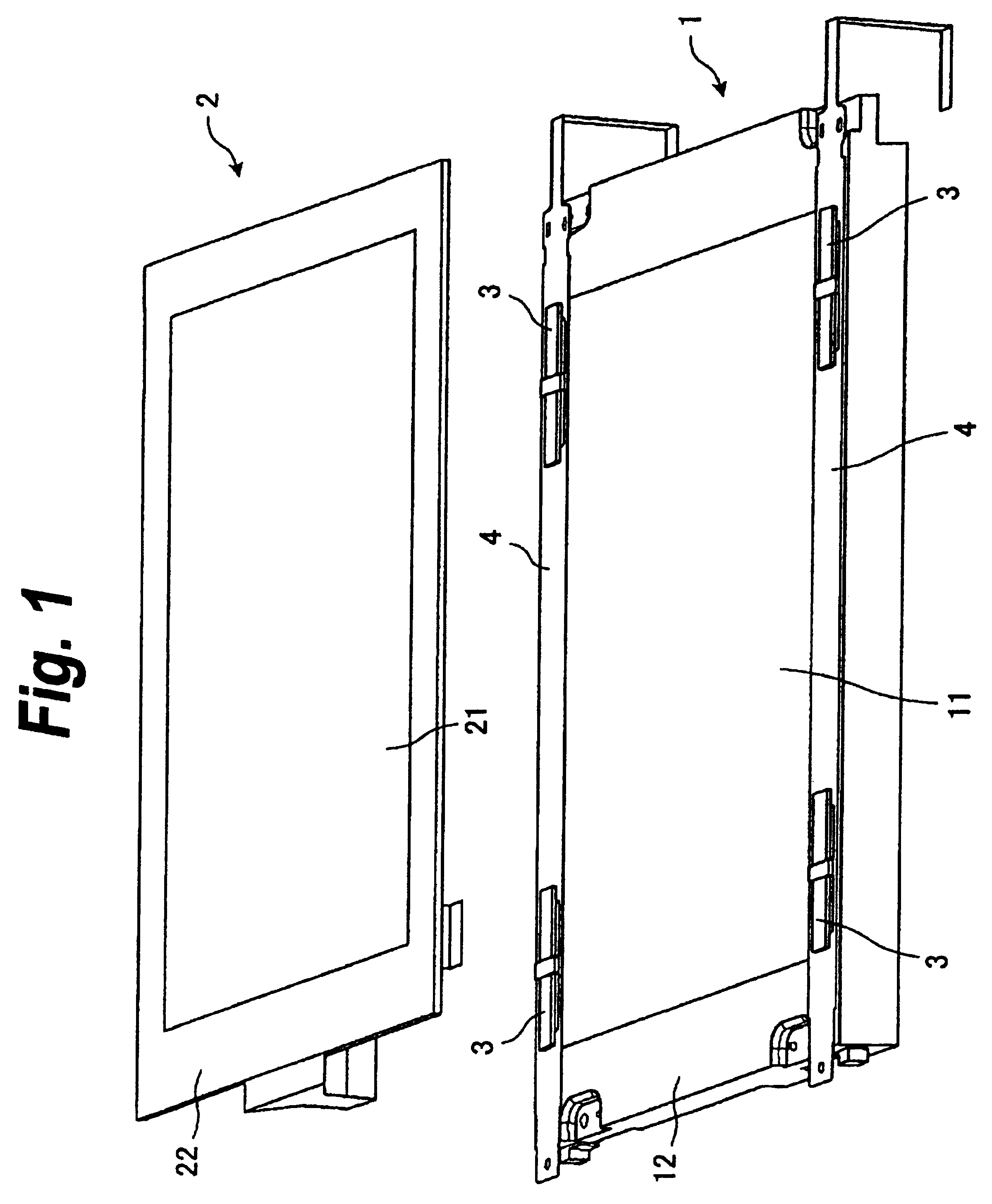
[0042]FIG. 1 is an exploded perspective view showing the structure of an input apparatus according to a first embodiment of the present invention.

[0043]The input apparatus shown in FIG. 1 is composed of a liquid crystal display portion 1 and a touch sensor portion 2. Fixed on the display side of the liquid crystal display portion 1 is a flexible board 4 on which a piezoelectric actuator 3 is mounted.

[0044]The liquid crystal display portion 1 comprises a display panel 11 and a frame 12. The display panel 11 displays a picture. The frame 12 holds the display panel 11. Disposed in the display panel 11 are a liquid crystal substrate, a backlight, and so forth (not shown). The frame 12 is made from for example a metal. The frame 12 is disposed on the display surface of the display panel 11 so that the frame 12 does not obstruct the display area of the picture.

[0045]The touch sensor portion 2 is an unit that has a sensor and so forth that detect whether the touch sensor portion 2 has been...

second embodiment

[0077]Next, as an example of a modification of the foregoing input apparatus, the case of which the piezoelectric actuator 3 is mounted on the flexible board 4 in the reverse direction of the foregoing inputting apparatus. FIG. 5 shows a mounting structure of a piezoelectric actuator 3 of an input apparatus according to a second embodiment of the present invention.

[0078]FIG. 5 is a side view showing the mounting structure of the piezoelectric actuator 3 on the flexible board 4. According to the second embodiment shown in this drawing, the piezoelectric actuator 3 is mounted on the opposite surface of the flexible board 4. Thus, when the piezoelectric actuator 3 is mounted, the center spacer portion 41c deforms toward the liquid crystal display portion 1. The center spacer portion 41c contacts the frame 12 of the liquid crystal display portion 1. Both the end portions of the piezoelectric actuator 3 contact the front surface of the flexible substrate 4. The rear surface of the flexib...

third embodiment

[0080]Next, an input apparatus having a simpler mounting structure of a piezoelectric actuator and a flexible substrate for higher production efficiency than the foregoing input apparatuses will be described.

[0081]FIG. 6 shows the structure of an input apparatus according to a third embodiment of the present invention. FIG. 6A shows the structure of a flexible board. FIG. 6B shows the structure of which a piezoelectric actuator has been mounted on the flexible board.

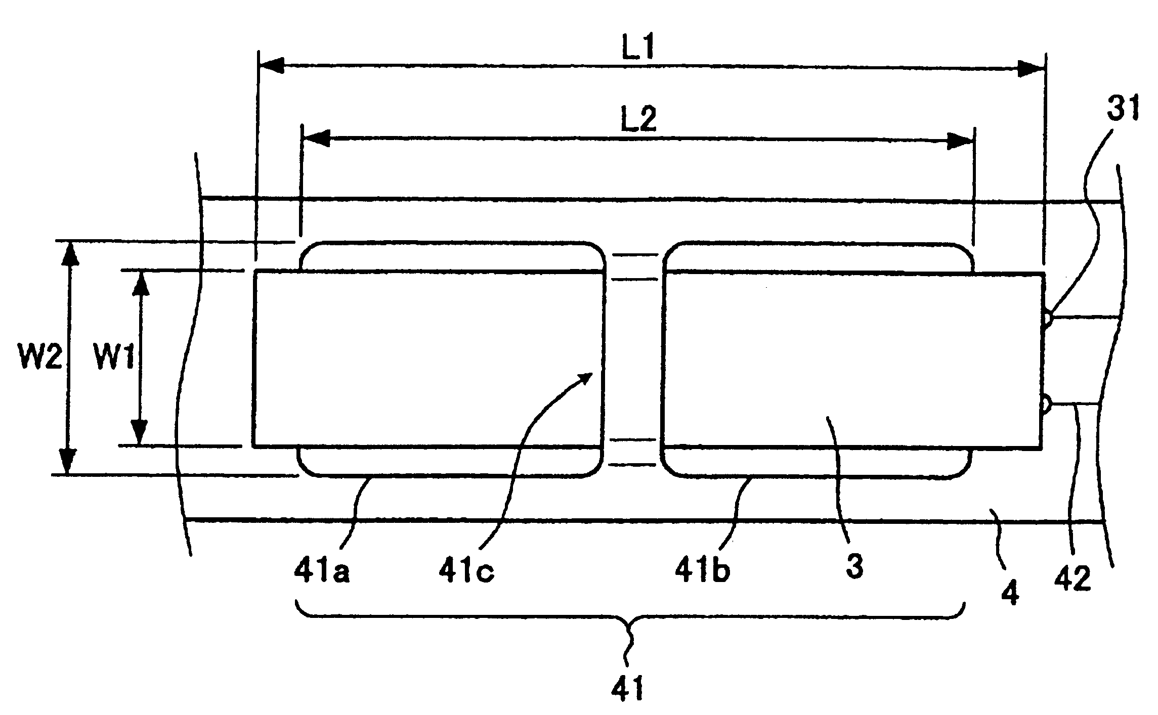
[0082]In a flexible board 14 shown in FIG. 6A, as a mounting portion 141 of a piezoelectric actuator 13, a pair of through-holes 141a and 141b are formed. In addition, a center spacer portion 141c is formed between the through-holes 141a and 141b. The center spacer portion 141c is straightly cut at a cut portion 141d. As shown in FIG. 6B, an end portion in the longitudinal direction of the piezoelectric actuator 13 contacts the upper surface of the flexible board 14 through the mounting portion 141. In addition, the cent...


PUM

PropertyMeasurementUnit
heightaaaaaaaaaa
drive voltageaaaaaaaaaa

Abstract

A pair of through-holes 41a and 41b having the same shape are formed and aligned in a flexible board 4 on which a wiring pattern 42 is formed. A piezoelectric actuator 3 made of a piezoelectric bi-morph device is inserted into the first through-hole 41a and then into the second through-hole 41b from the opposite surface side. As a result, both the ends in the longitudinal direction of the piezoelectric actuator 3 contact the same surface of the flexible board 4. The flexible board 4 is disposed so that it contacts a touch sensor portion except for a part of the flexible board 4. Thus, a high performance force sense feedback function caused by the panel that deforms corresponding to an input operation can be accomplished at low cost.

Description

TECHNICAL FIELD[0001]The present invention relates to an input apparatus for detecting whether a pressing operation or a touching operation has been performed on the front surface of a panel and inputting data corresponding to the detected result, a method for producing the input apparatus, and a portable electronic apparatus having the input apparatus, in particular, to an input apparatus having a function for moving a panel surface and feeding back a sense force, a method for producing the input apparatus, and a portable electronic apparatus having the input apparatus.[0002]This application is based upon and claims the benefit of priority from the prior Japanese Patent Application No. 2002-360608, filed on Oct. 30, 2002, the entire contents of which are incorporated herein by reference.BACKGROUND ART[0003]In recent years, input apparatuses called touch panels have been used for information processing apparatuses such as automatic teller machines in financial institution, ticketing...

Claims


Application Information

Patent Timeline
Patent Type & Authority Patents(United States)
IPC IPC(8): G06F3/033G06F3/00G06F3/01G06F3/02G06F3/041G06F3/042
CPCG06F3/016G06F3/0202G06F3/0421G06F3/0425G06F3/041Y10T29/42G06F2203/04103
Inventor INOKAWA, HIROYUKISATOH, KIMIYASU
Owner THOMSON LICENSING SA
Why Eureka
Try Eureka