Battery module, battery system and electric vehicle including the same

a battery module and battery technology, applied in the field of batteries, can solve the problems of large space of three dimensions for arranging the fuel cell including the signal processing module, complicated wiring, and difficulty in being reduced in size, and achieve the effect of reducing size and simplifying wiring

Inactive Publication Date: 2011-05-05
SANYO ELECTRIC CO LTD
View PDF5 Cites 58 Cited by
  • Summary
  • Abstract
  • Description
  • Claims
  • Application Information

AI Technical Summary

Benefits of technology

[0012]An object of the present invention is to provide a battery system whose wiring can be simplified and size can be reduced, and an electric vehicle including the same.

Problems solved by technology

The system using the battery pack and monitoring device of JP 8-162171 A and the battery system of JP 2009-168720 A, however, may result in complicated wiring and difficulty in being reduced in size.
However, arranging the fuel cell including the signal processing module requires large space of three dimensions.
Therefore, there is a limitation of space for arranging the fuel cell including the signal processing module.

Method used


Image

  • Battery module, battery system and electric vehicle including the same
  • Battery module, battery system and electric vehicle including the same
  • Battery module, battery system and electric vehicle including the same

Examples


first embodiment

[1] First Embodiment

[0100]Hereinafter, description will be made of a battery system according to a first embodiment by referring to the drawings. The battery system according to the present embodiment is mounted on an electric vehicle (an electric automobile, for example) using electric power as a driving source.

[0101](1) Configuration of the Battery System

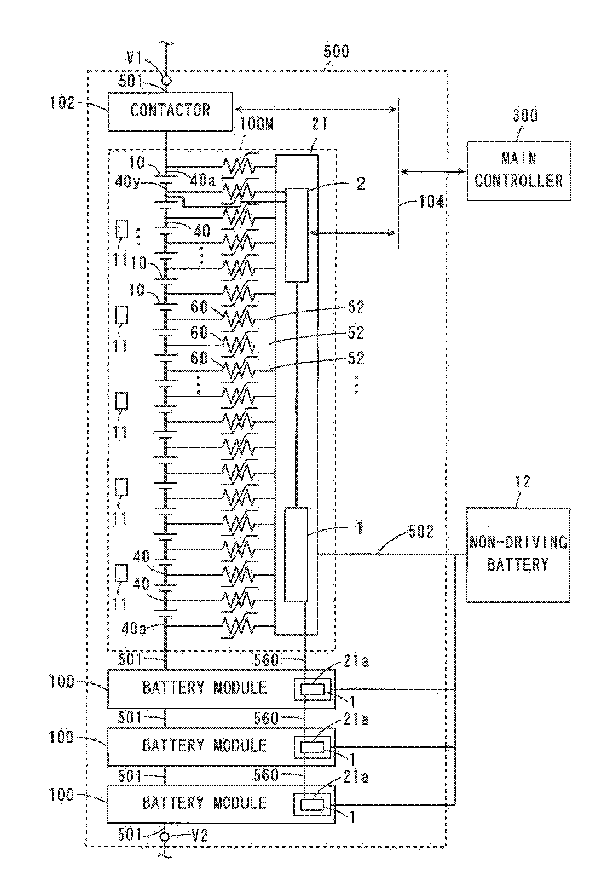
[0102]FIG. 1 is a block diagram showing the configuration of the battery system according to the first embodiment. As shown in FIG. 1, the battery system 500 includes a plurality of battery modules 100M, 100, and a contactor 102. In the present embodiment, the battery system 500 includes one battery module 100M and three battery modules 100.

[0103]The plurality of battery modules 100M, 100 of the battery system 500 are connected to one another through power supply lines 501. Each of the battery modules 100M, 100 includes a plurality of (eighteen in this example) battery cells 10 and a plurality of (five in this example) thermistors...

second embodiment

[2] Second Embodiment

[0213]Description will be made of a battery system according to a second embodiment by referring to differences from the battery system 500 according to the first embodiment.

[0214](1) Configuration of Main Circuit Board

[0215]FIG. 14 is a block diagram showing the configuration of a main circuit board 21 according to the second embodiment. Similarly to the first embodiment, the control-related circuit 2 as well as the cell characteristics detecting circuit 1 of FIG. 2 is mounted on the main circuit board 21. In the present embodiment, the control-related circuit 2 includes a total voltage detecting circuit 213, the insulating element 25b and a CAN communication circuit 203. The total voltage detecting circuit 213 includes a voltage detecting circuit 204 and the A / D converter 202, and the CAN communication circuit 203 includes an electric leakage detecting circuit 214.

[0216]In the present embodiment, the control-related circuit 2 has a total voltage detecting func...

third embodiment

[3] Third Embodiment

[0234]Description will be made of a battery system according to a third embodiment by referring to differences from the battery system 500 according to the first embodiment.

[0235](1) Configuration of Main Circuit Board

[0236]FIG. 17 is a block diagram showing the configuration of a main circuit board 21 in the third embodiment. Similarly to the first embodiment, the control-related circuit 2 as well as the cell characteristics detecting circuit 1 of FIG. 2 is mounted on the main circuit board 21. In the present embodiment, the control-related circuit 2 includes a contactor controlling circuit 215 and the CAN communication circuit 203.

[0237]In the present embodiment, the control-related circuit 2 has a contactor controlling function for controlling the contactor 102 to be turned on and off as a function related to control of the battery modules 100M, 100.

[0238]The main controller 300 applies the cell information of the plurality of battery modules 100M, 100 to the ...


PUM

PropertyMeasurementUnit
electric poweraaaaaaaaaa
torqueaaaaaaaaaa
voltageaaaaaaaaaa

Abstract

A battery system includes a plurality of battery modules each including a plurality of battery cells. One battery module includes a main circuit board, and the other battery modules include auxiliary circuit boards. The main circuit board includes a cell characteristics detecting circuit that detects characteristics of each battery cell and a control-related circuit having a function related to control of the plurality of battery modules. The auxiliary circuit board includes a cell characteristics detecting circuit that detects characteristics of each battery cell, and does not include a control-related circuit having the function related to control of the plurality of battery modules. In a battery module of another battery system, a first printed circuit board, a board holder and a second printed circuit board are attached to one end surface frame. A voltage detecting circuit that detects a voltage between terminals of each battery cell and a communication circuit having a communication function are mounted on the first and second printed circuit boards, respectively.

Description

BACKGROUND OF THE INVENTION[0001]1. Field of the Invention[0002]The present invention relates to a battery module, a battery system including a plurality of battery modules, and an electric vehicle including the same.[0003]2. Description of the Background Art[0004]In a battery system used as a driving source of a movable object such as an electric automobile, one or a plurality of chargeable and dischargeable battery modules are provided for supplying a driving force. Each of the battery modules has a battery block constituted by a plurality of batteries (battery cells) connected in series, for example, and a detecting circuit that detects a voltage of each battery cell.[0005]JP 8-162171 A discloses a monitoring device of a battery pack mounted on a movable object such as an electric automobile. The battery pack is composed of a plurality of modules, each of which includes a plurality of cells. The monitoring device includes a plurality of voltage measuring units connected to the pl...

Claims


Application Information

Patent Timeline
Patent Type & Authority Applications(United States)
IPC IPC(8): H02J7/00H01M10/48H01M50/209H01M50/284H01M50/503H01M50/505H01M50/51H01M50/522H01M50/526
CPCB60L11/1861G01R31/3658H01M2/1077H01M2/206H01M10/425H01M10/482Y02T10/7061H02J7/0021Y02T10/7055B60L11/1866Y02T10/7044Y02T10/7005Y02T90/16H01M10/486G01R31/396B60L58/22B60L58/15Y02T10/70Y02E60/10Y02P70/50H02J7/0048H02J7/005H02J7/0019H01M50/51H01M50/505H01M50/209H01M50/284H01M50/503H01M50/522H01M50/526
Inventor SEO, KAZUHIROKISHIMOTO, KEIJIOHKURA, KAZUMINISHIHARA, YOSHITOMOKUNIMITSU, TOMONORIMATSUBARA, TOMOYUKI
Owner SANYO ELECTRIC CO LTD
Why Eureka
Try Eureka