Check patentability & draft patents in minutes with Patsnap Eureka AI!

Touch control detection method

A detection method and touch technology, applied in the direction of instruments, electrical digital data processing, input/output process of data processing, etc., can solve the problem that the detection circuit cannot correctly compare the level difference, etc.

Inactive Publication Date: 2009-07-22
AU OPTRONICS CORP
View PDF0 Cites 4 Cited by
  • Summary
  • Abstract
  • Description
  • Claims
  • Application Information

AI Technical Summary

Problems solved by technology

[0007] Apparently, for such a case where the enabling pulses of two adjacent gate lines overlap by one scanning line, if the sensing line SL is still charged during the turn-on time of the gate line GL2m-1, due to this It is also the pre-turn-on time of the gate line GL2m, and the thin film transistor Q2 is turned on. If the sensing pad SP is electrically connected to the shared voltage Vcom due to being touched at this time, the sensing line SL will always leak and cannot be charged to Vref1. level, it will inevitably cause the detection circuit to be unable to correctly compare the level difference to determine whether the sensing pad SP is touched

Method used


Image

  • Touch control detection method
  • Touch control detection method
  • Touch control detection method

Examples


Embodiment Construction

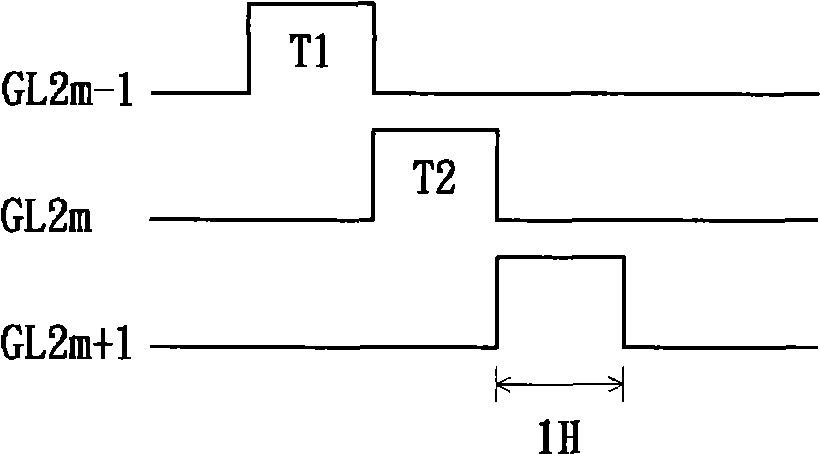
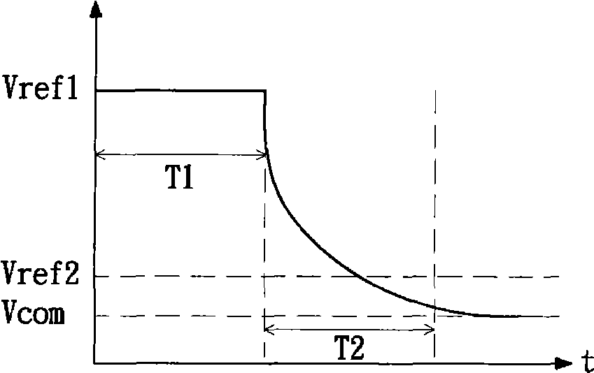
[0043] The following will combine Figure 4 to Figure 6 A touch detection method proposed by an embodiment of the present invention is specifically described, which is implemented in a display device in which the enabling pulses of two adjacent gate lines partially overlap.

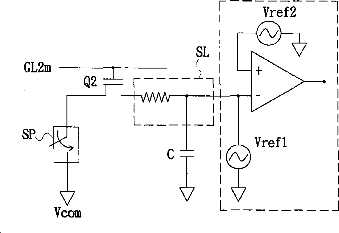
[0044] see Figure 4 , which shows a partial circuit diagram of the display device 10 with touch function related to the embodiment of the present invention. Such as Figure 4 As shown, the display device 10 includes a plurality of gate lines GL2n-1, GL2n and GL2n+1, a data line DL and a sensing line SL. The data line DL is intersected with the gate lines GL2n-1, GL2n and GL2n+1, and a pixel ( Figure 4not marked). Each pixel includes a thin film transistor Q1, a storage capacitor Cst and a liquid crystal capacitor Clc; the drain and gate of the thin film transistor Q1 are electrically coupled to the data line DL and the gate lines GL2n-1, GL2n and GL2n+1 respectively In the corresponding one, the st...


PUM


Abstract

The invention relates to a touch detection method which is executed on a display device. The display device comprises a first gate line, a sensing gasket and a second gate line adjacent to the first gate line. The sensing gasket is coupled with the first gage line electrically. The touch detection method comprises the steps as follows: the first gate line is enabled; and before the second gate line is enabled, whether the sensing gasket is touched is detected; wherein, the time that the subsequent second gate line is under the state of being enabled and the time that the first gate line is under the state of being enabled are partially superimposed. The detection operation is set within the time that a previous gate line of the gate line which is coupled with the sensing gasket / sensing line electrically is started and / or before a latter gate line is enabled, and correspondingly, the charging operation is brought forward to be executed before the gate line which is coupled with the sending gasket / sensing line electrically is enabled, thereby ensuring that the charging operation of the sensing line can not be influenced by the touch operation and being applicable to the display device where pulses of two adjacent gate lines have partial time superimposed.

Description

technical field [0001] The present invention relates to the field of touch detection, and in particular to a touch detection method. Background technique [0002] see Figure 1 to Figure 3 , figure 1 It shows a timing diagram of signals on multiple gate lines GL2m-1, GL2m and GL2m+1 of a display device with touch function in the prior art, figure 2 An equivalent circuit diagram showing a sensing line SL and a detection circuit electrically coupled to the gate line GL2m, image 3 The charging and discharging process of the sensing line SL is shown. [0003] Such as figure 2 As shown, the gate line GL2m is electrically coupled to the gate of the TFT Q2, the drain of the TFT Q2 is electrically coupled to the sensing line SL, and the source of the TFT Q2 is electrically coupled to a sensing pad. SP, there is a parasitic capacitance C between the sensing line SL and the shared voltage Vcom, and the sensing pad SP is electrically connected to the shared voltage Vcom when to...

Claims


Application Information

Patent Timeline
IPC IPC(8): G06F3/041
Inventor 陈振铭贾邦强
Owner AU OPTRONICS CORP
Features
  • R&D
  • Intellectual Property
  • Life Sciences
  • Materials
  • Tech Scout
  • Unparalleled Data Quality
  • Higher Quality Content
  • 60% Fewer Hallucinations
Learn More