Metallic catalyst support with slit pore

A technology of catalyst carrier and porous metal, which is applied in the direction of catalyst carrier, physical/chemical process catalyst, chemical instrument and method, etc., can solve the problems of durability reduction, honeycomb body tearing, etc., and achieve the effect of improving durability

Inactive Publication Date: 2009-08-05
CALSONIC KANSEI CORP
View PDF1 Cites 4 Cited by
  • Summary
  • Abstract
  • Description
  • Claims
  • Application Information

AI Technical Summary

Problems solved by technology

[0006] Therefore, there is a problem that the slit holes of the metal foil arranged on the outermost periphery of the honeycomb body inside the brazing material are connected like tear lines to tear the honeycomb body and reduce the durability.

Method used


Image

  • Metallic catalyst support with slit pore
  • Metallic catalyst support with slit pore
  • Metallic catalyst support with slit pore

Examples


Embodiment 1

[0018] Embodiment 1 will be described below.

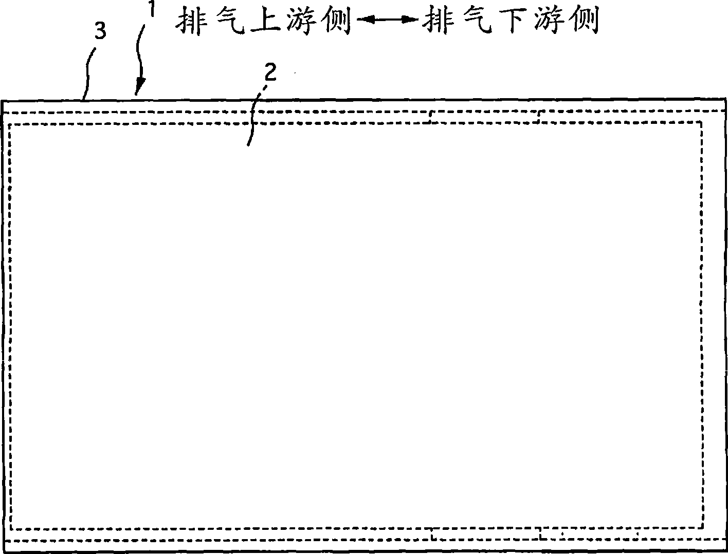
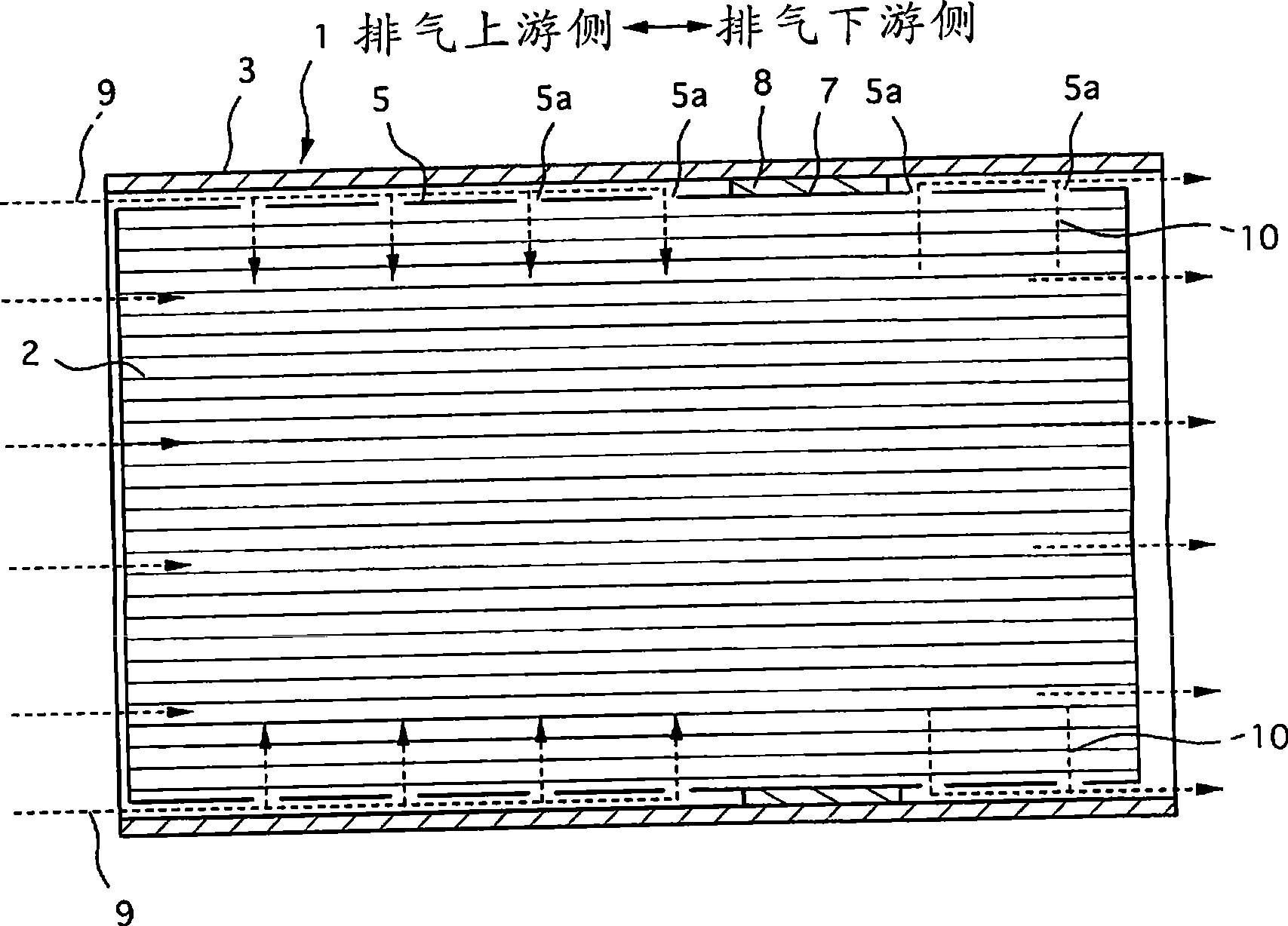
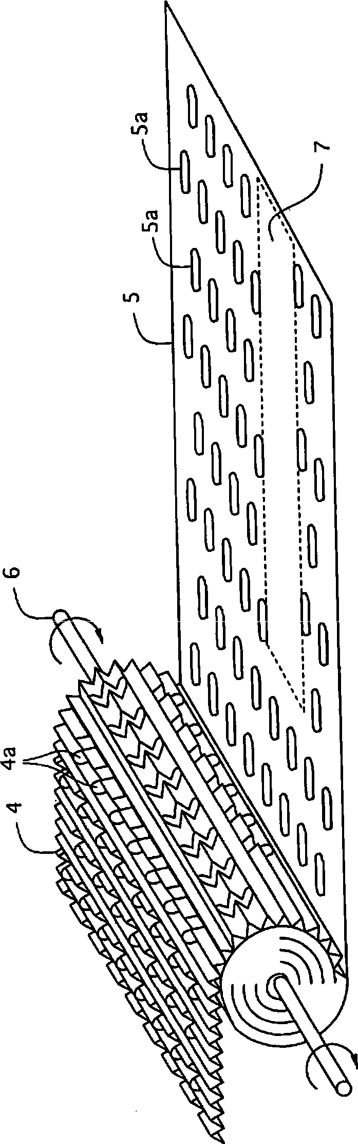
[0019] figure 1 is a side view of the metal catalyst carrier of Example 1, figure 2 is a side sectional view of the metal catalyst carrier, image 3 is a diagram illustrating the manufacture of the honeycomb body of Example 1, Figure 4 is a perspective view of the honeycomb body of Example 1, Figure 5 It is a perspective view of the honeycomb body of Example 1 in which foil-shaped brazing filler metal is provided.

[0020] First, the overall structure will be described.

[0021] Such as figure 1 , 2 As shown, the metal catalyst carrier 1 of Example 1 is composed of a metal cylindrical honeycomb body 2, a metal cylindrical outer cylinder 3 for accommodating the honeycomb body 2, and the like.

[0022] Such as image 3 As shown, the honeycomb body 2 is made by fixing the respective starting ends of the corrugated metal foil 4 and the flat metal foil 5 on the reel 6 of the winding machine, and then wrapping the two metal f...


PUM


Abstract

The invention provides a metal catalyst carrier having slit pore capable of obtaining effect of spreading the exhaust gas generated by slit pore of metal leaf at outermost periphery, while preventing the metal leaf from tearing along the heat expansion and heat contraction of the honeycomb ceramics, thereby improving durability. The metal catalyst carrier comprises a roller honeycomb ceramic (2) and a barrel-shaped outer cylinder (3) for containing the honeycomb ceramic (2); the honeycomb ceramic (2) is formed by winding undulatory metal leaf (4) and tabulate metal leaf (5) into a plurality of layer under the condition of overlapping the same; the slit pores (4a, 5a) are provided on theundulatory metal leaf (4) and tabulate metal leaf (5); by aid of brazing filler metal (brazing foil (8)), a part of periphery (7) of the honeycomb ceramic (2) and the outer cylinder (3) are fixed; the slit pore (5a) at the metal leaf (5) at outermost periphery of the honeycomb ceramic (2) is arranged at the position except from the part of periphery (7).

Description

technical field [0001] The invention relates to a metal catalyst carrier with slit holes. Background technique [0002] Conventionally, as an exhaust purification device for an internal combustion engine, a metal catalyst carrier with slit holes is known. The roll-shaped honeycomb body is formed by winding multiple layers of corrugated metal foil and small corrugated or flat metal foil; in corrugated metal foil and small corrugated or flat metal foil A slit hole is set on any one of the metal foils, and a part of the outer periphery of the honeycomb body and the outer cylinder are fixed by means of solder. [0003] Patent Document 1: Japanese Patent Laid-Open No. 2004-154699 [0004] However, in the conventional invention, since the heat capacity difference between the outer cylinder and the honeycomb body is fixed by brazing filler metal to fix a part of the outer periphery of the honeycomb body and the outer cylinder, the high-temperature exhaust gas of the internal comb...

Claims


Application Information

Patent Timeline
Patent Type & Authority Applications(China)
IPC IPC(8): B01J35/04B01J32/00
Inventor 儿玉博史
Owner CALSONIC KANSEI CORP
Why Eureka
Try Eureka