Rear vision system with automatic blind zone and glare elimination function

A blind spot and glare technology, applied in the system field of automatic switching of vehicle side mirrors, can solve the problem of driver distraction

Inactive Publication Date: 2009-08-05
GM GLOBAL TECH OPERATIONS LLC
View PDF0 Cites 2 Cited by
  • Summary
  • Abstract
  • Description
  • Claims
  • Application Information

AI Technical Summary

Problems solved by technology

However, driver distraction may be a concern as the vehicle operator is required to move his head while driving to complete the

Method used


Image

  • Rear vision system with automatic blind zone and glare elimination function
  • Rear vision system with automatic blind zone and glare elimination function
  • Rear vision system with automatic blind zone and glare elimination function

Examples


Embodiment Construction

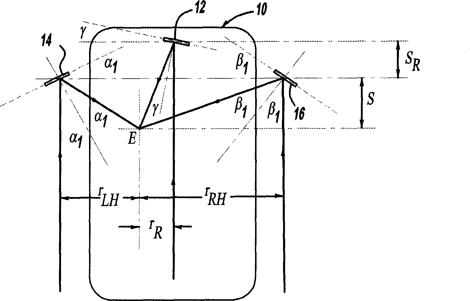
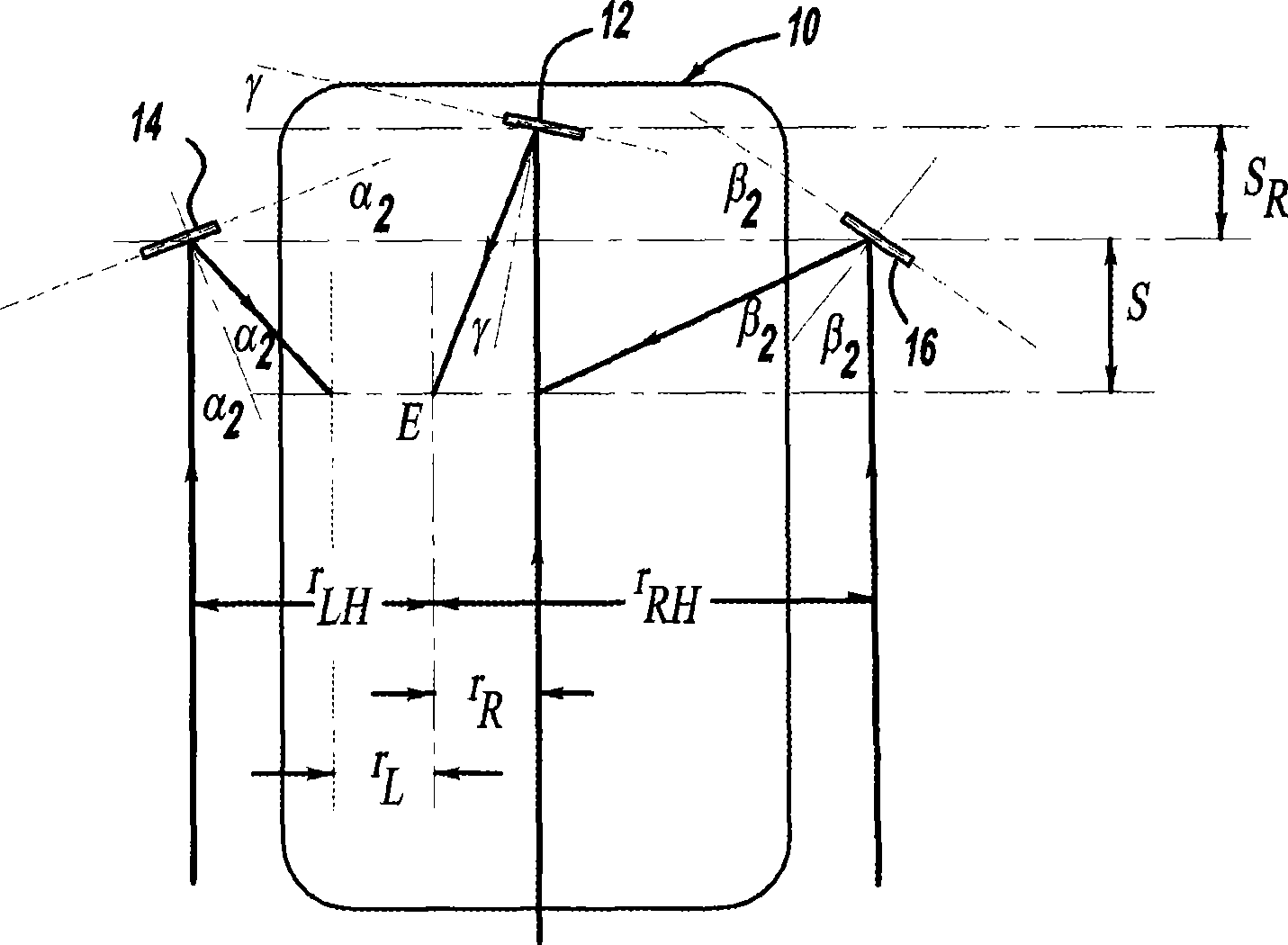
[0012] The following description of an embodiment of the invention for the process of automatically switching between the blind spot side mirror setting position and the blind spot / glare canceling side mirror setting position is merely exemplary in nature and is in no way intended to limit the invention or its applications or use.

[0013] figure 1 and figure 2 is a plan view of a vehicle 10 including an interior rearview mirror 12 , a driver's side mirror 14 and a passenger's side mirror 16 . Point E represents the position of the driver's eyes during normal driving, and S is the distance in the forward direction from the driver's eyes to the driver's side mirror 14 . variable r LH is the lateral distance between point E and the driver's side mirror 14, variable r RH is the lateral distance between the driver's eyes and the passenger's side mirror 16, the variable r R is the lateral distance between the driver's eyes and the rearview mirror 12, the variable r R is the ...


PUM


Abstract

A system for automatically changing the position of the side mirrors of a vehicle between a blind zone side mirror setting position and a blind zone / glare elimination (BGE) side mirror setting position in response to actuation of a switch. From the angle of the driver side mirror an equation can be used to determine the distance between the driver side mirror and the vehicle operator's eyes. Based on the angle of the driver side mirror, the system will know whether the driver set the driver side mirror for the blind zone setting method or the BGE setting method. If the vehicle operator actuates the switch, then the system will use the distance from the vehicle operator's eyes to the driver side mirror to set the angle for the other of the blind zone setting method or the BGE setting method based on predetermined equations.

Description

technical field [0001] The present invention relates to a system for setting the angle of a vehicle side mirror, and more particularly, to a system for automatically switching a vehicle side mirror between a blind spot side mirror set position and a blind spot / glare canceling side mirror set position in response to vehicle operator input system. Background technique [0002] It is known in the art to automatically adjust the position of the passenger's side mirror and the vehicle's interior rearview mirror in response to angular adjustments made by the vehicle operator to the driver's side mirror. The system determines the vehicle operator's eye position based on the angle of the driver's side mirror, and then adjusts the position of the passenger's side mirror or interior rearview mirror based on the eye position. [0003] Typically, the vehicle operator angles the vehicle's side mirrors at a position that defines blind spots on both sides of the vehicle. In the art, this...

Claims


Application Information

Patent Timeline
Patent Type & Authority Applications(China)
IPC IPC(8): B60R1/06G02B5/08
CPCB60R1/02
Inventor 王震台
Owner GM GLOBAL TECH OPERATIONS LLC
Why Eureka
Try Eureka