Head hood for endoscope and endoscope with hood

A technology for endoscopes and front-end hoods, which is applied in the fields of endoscopes, telescopes, and medical sciences, and can solve problems such as difficult elastic deformation, hood obstacles, and magnified observation of living tissue surfaces

Inactive Publication Date: 2009-08-19
OLYMPUS CORP
View PDF2 Cites 15 Cited by
  • Summary
  • Abstract
  • Description
  • Claims
  • Application Information

AI Technical Summary

Problems solved by technology

However, when the cover of the above-mentioned Patent Document 1 is assembled on an endoscope having an object contact type observation optical system that makes the tip of the objective optical system contact an object to observe the object like Patent Document 2, the cover becomes Obstacles, making it difficult to bring the tip of the objective optical system into contact with the object
In addition, the cover of the elastic body of the above-mentioned Patent Document 1 is relatively soft, and when the front end portion of the cover is pressed on the living tissue, it is in soft and close contact without damaging the living tissue, so it is difficult to elastically deform the front end portion of the objective optical system. The position of the contact object
[0005] In addition, since the cover is not disclosed in the endoscope of Patent Document 2, it is difficult to maintain a constant distance between the position of the observation lens of the ordinary observation optical system and the surface of the living tissue when observing with the ordinary observation optical system.
Therefore, it is difficult to magnify and observe the surface of the living tissue while keeping the distance between the position of the observation lens of the general observation optical system and the surface of the living tissue constant.
Therefore, there is a problem that it is difficult to stably perform magnified observation of the surface of living tissue with an ordinary observation optical system.

Method used


Image

  • Head hood for endoscope and endoscope with hood
  • Head hood for endoscope and endoscope with hood
  • Head hood for endoscope and endoscope with hood

Examples


Embodiment Construction

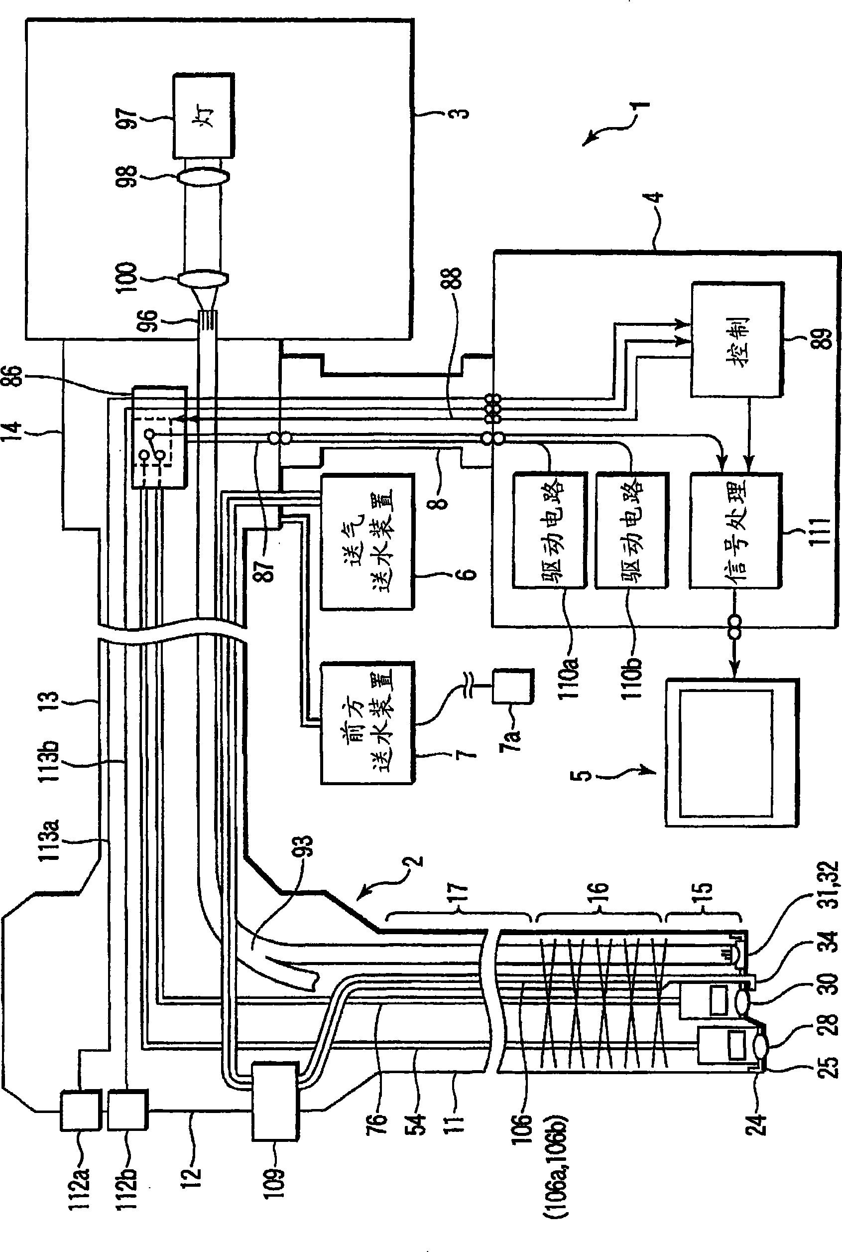
[0075] Below, refer to Figure 1 ~ Figure 6C The first embodiment of the present invention will be described. figure 1 The schematic structure of the whole endoscope system 1 of this embodiment is shown. Such as figure 1 As shown, the endoscope system 1 of the present embodiment includes: an endoscope 2; a light source device 3 as an illumination unit for supplying illumination light to the endoscope 2; and a signal processing device for performing signal processing on the endoscope 2. A processor 4; a monitor 5 connected to the processor 4; an air and water supply device 6 for supplying air and water; and a front water supply device 7 for forward water supply.

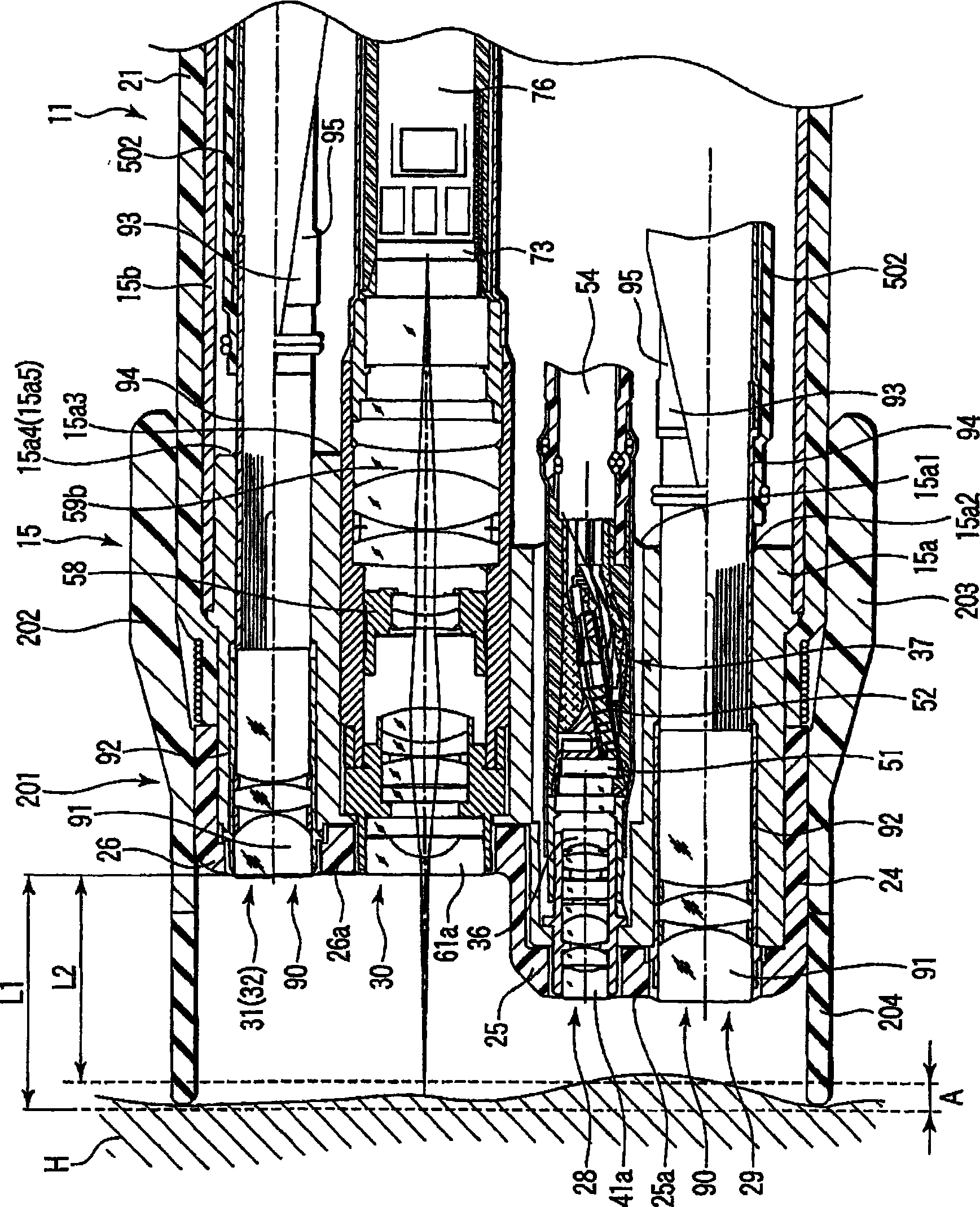
[0076] The endoscope 2 has: an elongated insertion portion 11 inserted into a body cavity; an operation portion 12 connected to the proximal end of the insertion portion 11 ; and a universal cable 13 extending from the side of the operation portion 12 . The connector 14 provided at the end of the universal cable 13...


PUM


Abstract

An elastically deformable elastic deformation portion (204) is disposed at a distal end portion of a cylindrical hood main body (202) attached on an outer peripheral surface of a distal end portion (15) of an endoscope (2), and the elastic deformation portion (204) is configured such that a distal end portion of the elastic deformation portion (204) abuts on an analyte to position an observation position of a second imaging unit (30) at a magnification observation time utilizing the second imaging unit (30) while the elastic deformation portion (204) is elastically deformable up to a position where a first imaging unit (28) abuts on an analyte at a contact observation time utilizing the first imaging unit (28). Thereby, a distal end hood for an endoscope where observation of a surface of a body tissue utilizing an ordinary observation optical system can be performed stably even by an endoscope provided with the observation optical system of an object contact type where observation is performed in a contact state with a body tissue, and object contact observation where observation is performed in a contact state of the observation optical system of an object contact type with a body tissue can be performed stably, and an endoscope with a hood are provided.

Description

technical field [0001] The present invention relates to a front end cover of an endoscope having an object contact type observation optical system for observing an object by bringing the end portion of an objective optical system into contact with the object, and an endoscope with a cover. Background technique [0002] Japanese Unexamined Patent Application Publication No. Sho 55-84141 (Patent Document 1) describes an endoscope in which a cover is provided at the distal end portion of an insertion portion of the endoscope. Here, the distance between the front end surface of the insertion portion and the surface of the living tissue is kept constant by pressing the front end portion of the cover against the living tissue. In the endoscope disclosed in Patent Document 1, the cover is formed of an elastic body. Thus, when the front end portion of the cover is pressed against the living tissue, the living tissue will not be damaged due to soft and close contact. [0003] Japan...

Claims


Application Information

Patent Timeline
Patent Type & Authority Applications(China)
IPC IPC(8): A61B1/00G02B23/24
CPCA61B1/00089G02B23/2438G02B23/2476A61B1/00096A61B1/00181A61B1/00188A61B1/04A61B1/012A61B1/01
Inventor 一村博信
Owner OLYMPUS CORP
Why Eureka
Try Eureka