Washing tube and endoscope washing and disinfecting apparatus
A technology for cleaning and disinfecting endoscopes, which is applied in the field of cleaning pipes and can solve problems such as pipe blockage, inability to control the flow of cleaning water, and inability to use the flow control function.
- Summary
- Abstract
- Description
- Claims
- Application Information
AI Technical Summary
Problems solved by technology
Method used
Image
Examples
no. 1 Embodiment approach
[0030] First, according to Figure 1 to Figure 10 The first embodiment of the present invention will be described.
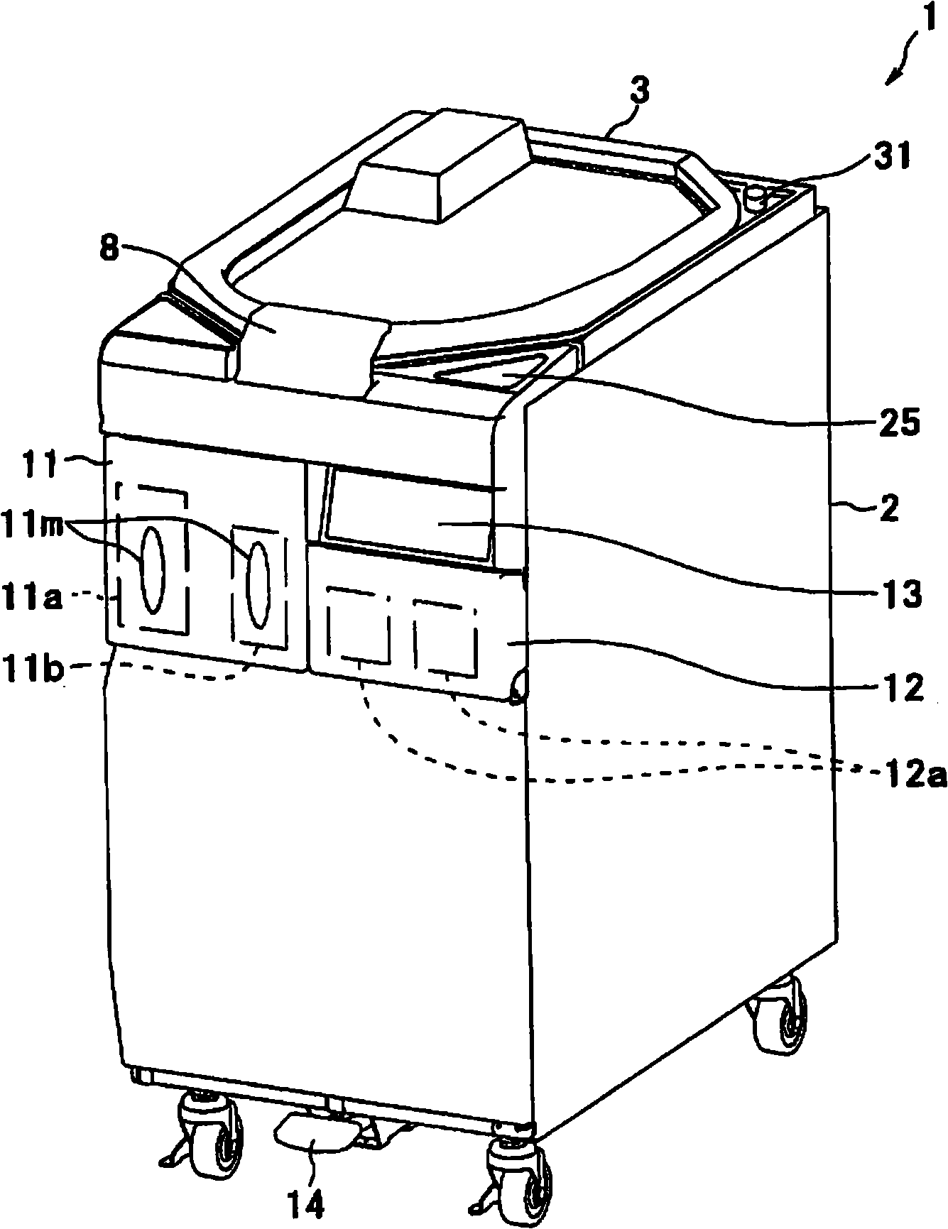
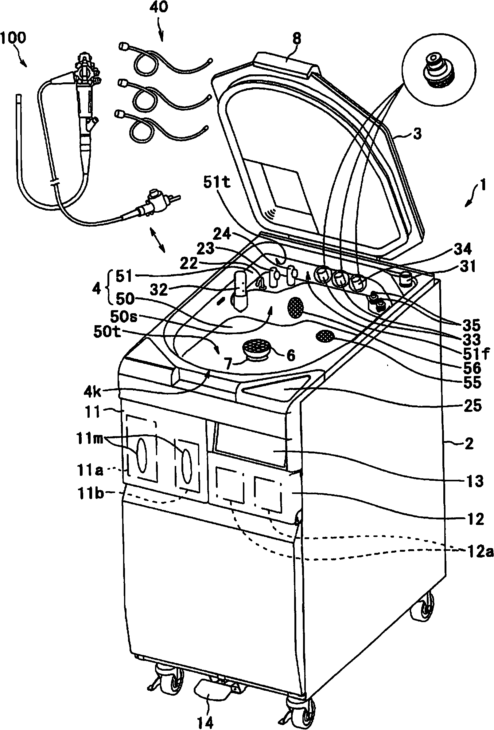
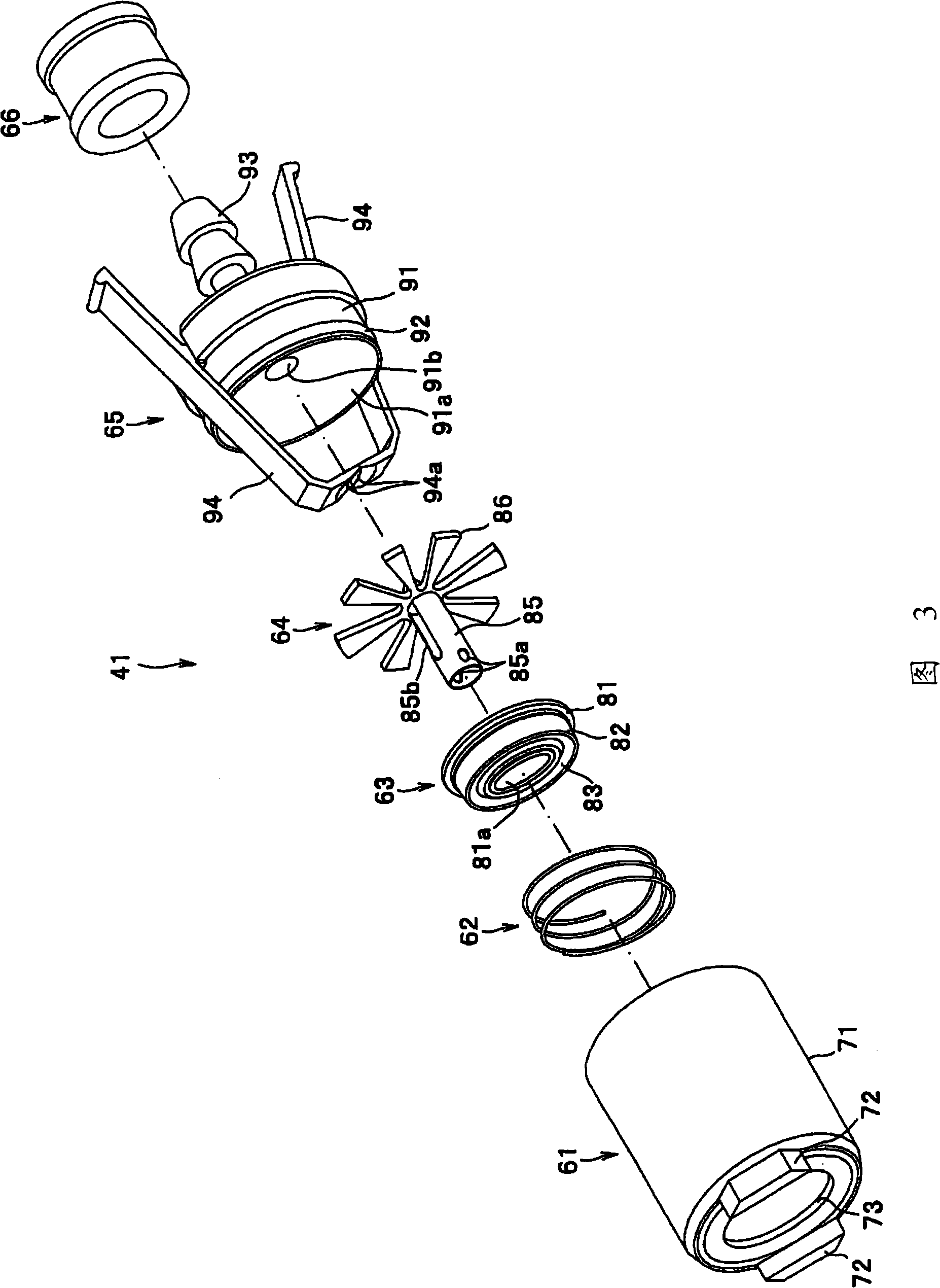
[0031] Figure 1 to Figure 10 Regarding the first embodiment of the present invention, figure 1 It is a three-dimensional view of the endoscope cleaning and disinfection device, figure 2 yes means figure 1 The perspective view of the endoscope cleaning and disinfection device with the top cover open and the endoscope freely accommodated in the cleaning and disinfection tank, image 3 It is an exploded perspective view showing the endoscope-side connector portion of the cleaning tube, Figure 4 is a sectional view of the housing body of the front housing, Figure 5 is the main body of the shell Figure 4 The V-V sectional view in, Image 6 is a sectional view showing the endoscope-side connector portion of the cleaning tube, Figure 7 It is a cross-sectional view for explaining the function of attaching the endoscope-side connector part to the tube head ...
no. 2 Embodiment approach
[0082] Next, according to Figure 11 A second embodiment of the present invention will be described. Figure 11 A second embodiment of the present invention is a schematic view showing a pipeline structure for supplying alcohol from an alcohol container to a channel of an endoscope.
[0083] In the following description, the same reference numerals are used for the same configurations as those of the endoscope cleaning and disinfection apparatus 1 of the first embodiment described above, and detailed descriptions of the configurations are omitted.
[0084] However, as is well known, conventional endoscope cleaning and disinfecting apparatuses perform an alcohol rinsing process to promote drying of the inside of the endoscope channel. In this alcohol rinsing process, the conventional endoscope cleaning and disinfection device uses an alcohol pump to send the alcohol stored in the alcohol container to the MIX area (block) in the device, and uses a compressor to deliver it to ea...
no. 3 Embodiment approach
[0095] Next, according to Figure 12 to Figure 16 A third embodiment of the present invention will be described. in addition, Figure 12 to Figure 16 Regarding the third embodiment of the present invention, Figure 12 It is a partial cross-sectional view showing the structure of an endoscope tube automatic loading and unloading mechanism that moves in two directions up and down by a motor to advance and retreat toward the tube head of the endoscope. Figure 13is a partial sectional view showing the structure of the nozzle unit, Figure 14 is a partial sectional view for explaining the function of the nozzle unit, Figure 15 is a partial cross-sectional view showing the structure of a nozzle unit of a modified example, Figure 16 is for illustration Figure 15 Partial cross-sectional view of the role of the nozzle unit.
[0096] In the following description, the same reference numerals are used for the same configurations as those of the endoscope cleaning and disinfectio...
PUM
 Abstract
Description
Claims
Application Information
 - R&D
- Intellectual Property
- Life Sciences
- Materials
- Tech Scout
- Unparalleled Data Quality
- Higher Quality Content
- 60% Fewer Hallucinations
Browse by: Latest US Patents, China's latest patents, Technical Efficacy Thesaurus, Application Domain, Technology Topic, Popular Technical Reports.
© 2025 PatSnap. All rights reserved.Legal|Privacy policy|Modern Slavery Act Transparency Statement|Sitemap|About US| Contact US: help@patsnap.com


