Variable turbo supercharger and method of driving the same

A turbocharger, a variable technology, applied in the direction of machines/engines, fluid pressure actuators, mechanical equipment, etc., can solve the problems of taking up more space, the slide valve is easily affected by the flow force, and is not so large , to achieve the effect of a simple structure

Inactive Publication Date: 2009-09-02
KOMATSU LTD
View PDF2 Cites 1 Cited by
  • Summary
  • Abstract
  • Description
  • Claims
  • Application Information

AI Technical Summary

Problems solved by technology

Therefore, in this structure, the spool valve for position control is balanced by electromagnetic thrust and spring load, and since a large amount of hydraulic oil for driving the servo piston flows through the spool valve and the spring load is not so large, the spool valve moves easily Affected by flow forces, precise position control of spool valves is limited
And when the electromagnetic thrust is increased in order to increase the spring load, the problem that the size of the electromagnetic coil becomes larger and takes up more space occurs.

Method used


Image

  • Variable turbo supercharger and method of driving the same
  • Variable turbo supercharger and method of driving the same
  • Variable turbo supercharger and method of driving the same

Examples


Embodiment Construction

[0046] An embodiment of the present invention will be described below based on the drawings.

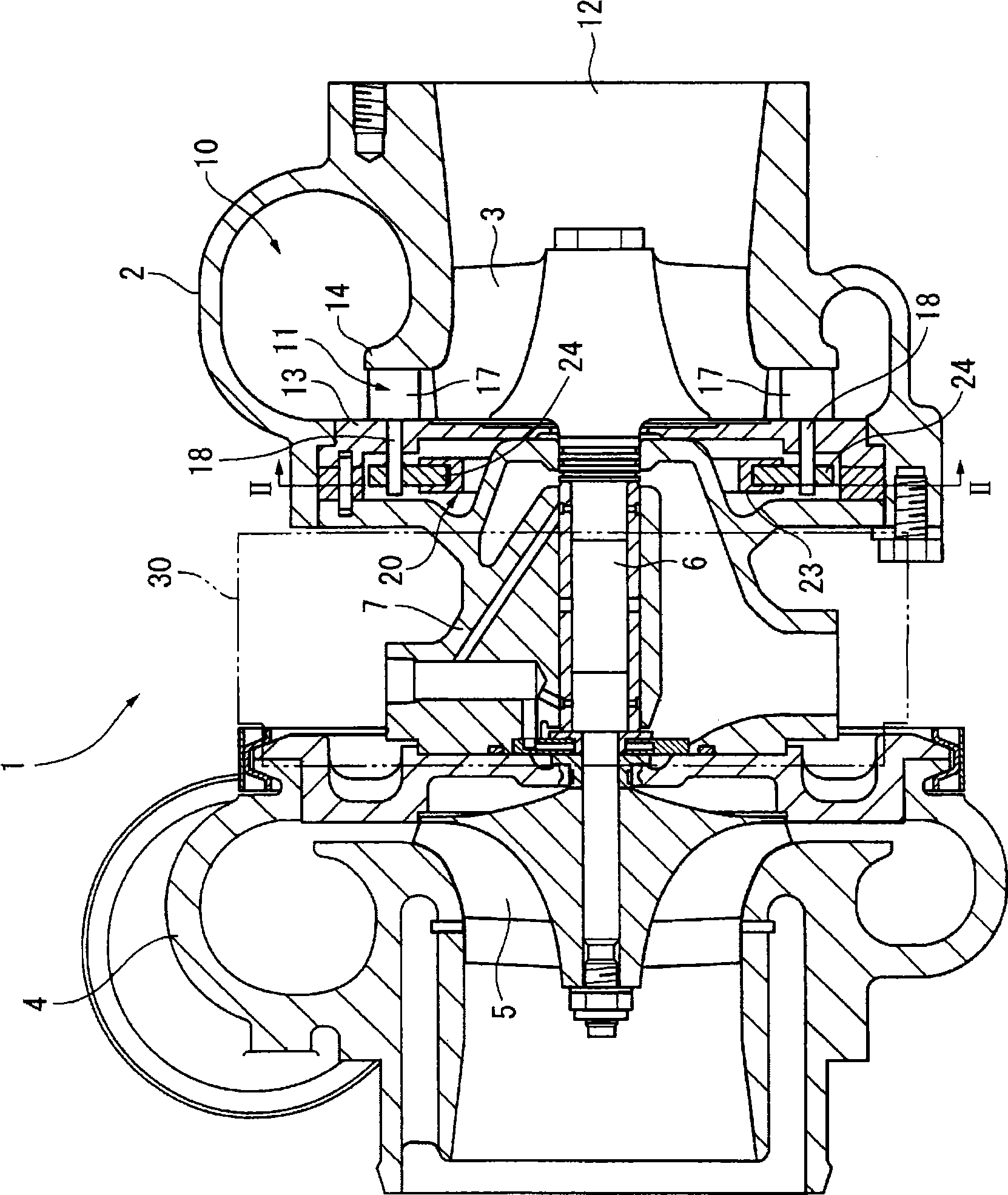
[0047] figure 1 It is a sectional view of the variable turbocharger 1 of this embodiment. The variable turbocharger 1 is provided in an engine body not shown in the figure, and has a turbine on the right side in the figure and a compressor on the left side. The turbine 3 is accommodated in a turbine housing 2 on the turbine side, and the compressor impeller 5 is accommodated in a compressor housing 4 on the compressor side. The shaft 6 is integrated with the turbine 3 , and the compressor impeller 5 is mounted on the front end of the shaft 6 . The shaft 6 is rotatably supported by the center case 7 . Therefore, the rotation of the turbine 3 rotated by the exhaust gas is transmitted to the compressor impeller 5 via the shaft 6 , and the intake gas is compressed and supercharged by the rotation of the compressor impeller 5 .

[0048] The turbine casing 2 is provided with a scroll-s...


PUM


Abstract

The present invention relates to a variable turbo supercharger. A hydraulic servo drive device (30) for driving a swing mechanism of the variable supercharger is constructed from a servo piston (31) connected to a drive shaft (21) of the swing mechanism and from a pilot spool (36) received in a center hole (34) of the servo piston (31) and slid by pilot pressure. A first hydraulic chamber (47) and second hydraulic chamber (48) into and from which pressurized oil flows are arranged in a housing (33). In the servo piston (31) are separately arranged a pressure port (51) into which pressurized oil flows from the outside, a first piston port (53) for interconnecting the center hole (34) and the first hydraulic chamber (47), a second piston port (54) for interconnecting the center hole (34) and the second hydraulic chamber (48), and a return port (52) from which pressurized oil flows.

Description

technical field [0001] The invention relates to a variable turbocharger and a driving method thereof. Background technique [0002] Conventionally, there is known a variable turbocharger in which movable nozzle vanes are provided on the nozzle portion of the exhaust turbine, and the opening degree of the nozzle (the opening area of ​​the nozzle portion) can be adjusted by rotating the nozzle vane. ). According to such a variable turbocharger, it is only necessary to rotate the nozzle vane to reduce the opening degree of the nozzle in the low-speed rotation region of the engine where the amount of exhaust gas is small, and since this increases the flow velocity of the exhaust gas flowing into the exhaust turbine, Therefore, the rotational energy of the exhaust gas turbine can be increased, thereby improving the supercharging capability of the air supply compressor. [0003] As a specific structure for rotating the nozzle vanes, there is known a structure in which a drive sh...

Claims


Application Information

Patent Timeline
Patent Type & Authority Applications(China)
IPC IPC(8): F02B37/24F01D17/16F01D25/24F15B13/042
CPCF05D2260/50F05D2260/406F05D2220/40F05B2220/40F15B15/204F01D17/165F05B2260/50F05B2260/406F01D17/16F01D25/24F02B37/24F15B13/042F15B13/0426
Inventor 西山利彦堀秀司饭野任久小塚大辅
Owner KOMATSU LTD
Why Eureka
Try Eureka