Interference overload indication generating method, interference overload indication triggering method, interference overload indication method and base station
A technology of interference overload indication and interference overload, applied in the directions of payload distribution, transmission monitoring, transmission path separation device, etc., can solve the problems of high signaling overhead and unreasonable trigger mechanism.
- Summary
- Abstract
- Description
- Claims
- Application Information
AI Technical Summary
Problems solved by technology
Method used
Image
Examples
example 1
[0163] Example 1: Signaling of an interference overload coded sequence. Directly use the interference overload coding sequence as the signaling of the interference overload indication (step S510).
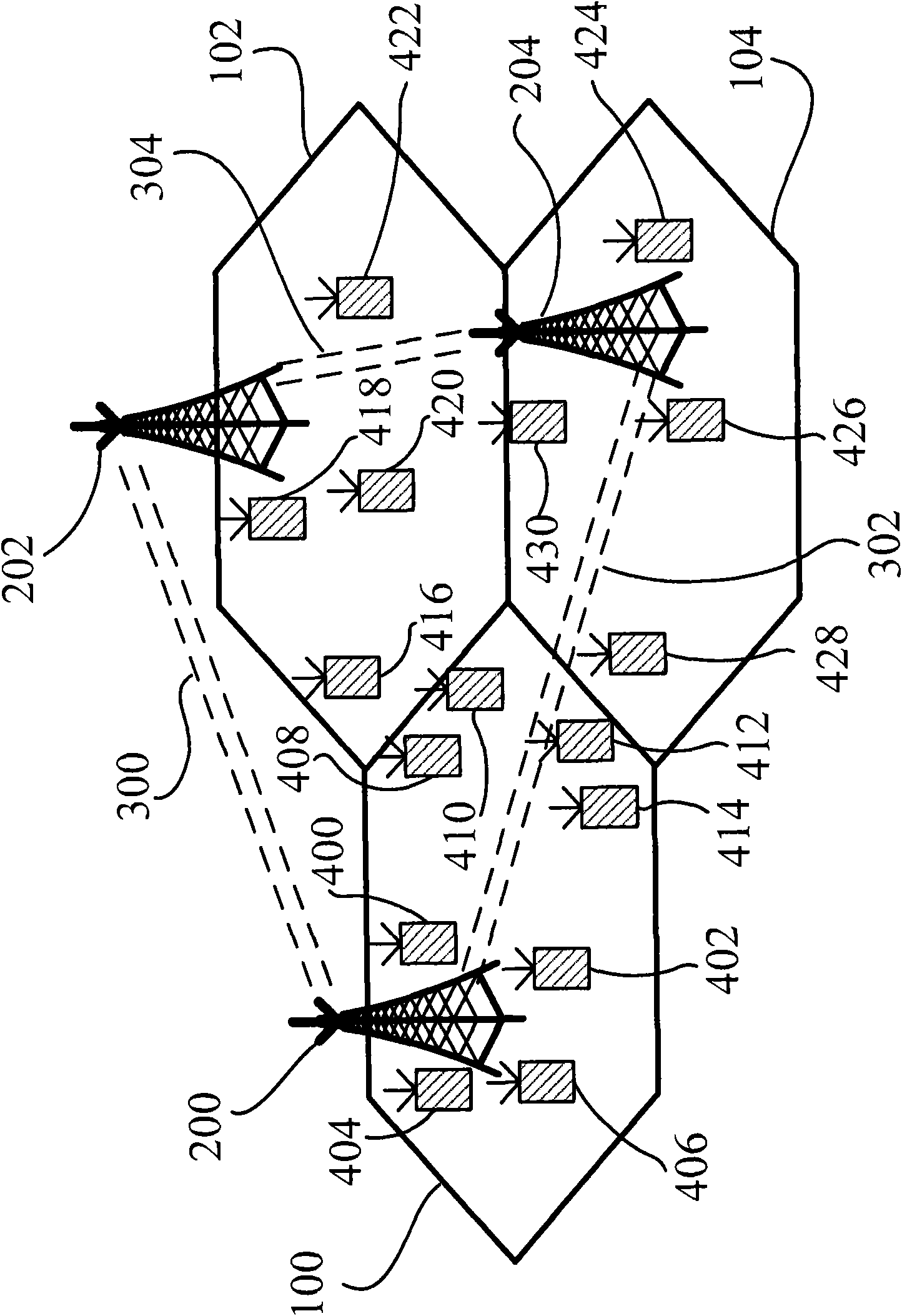
[0164] use image 3 In the interference overload scenario shown, the schematic diagram of this embodiment is shown in Figure 5 shown. For spectrum resource blocks 1 to 10, the interference overload code on each spectrum resource block is 2 bits, and the signaling for interference overload indication is formed by cascading the interference overload codes of spectrum resource blocks 1 to 10, namely "01000001111000000000" , and its signaling overhead is 20 bits.
[0165] The base station that receives the interference overload indication combines the bit sequences in pairs into an interference overload code, and then decodes it according to Table 1, and obtains the interference overload levels of spectrum resource blocks 1 to 10 as "low, none, none, low , High, Medium, None, None...
example 2
[0167] Example 2: Signaling of an interference overload coded sequence. Directly use the interference overload coding sequence as the signaling of the interference overload indication (step S510).
[0168] use Figure 4 In the interference overload scenario shown, the schematic diagram of this embodiment is shown in Image 6 shown. For spectrum resource blocks 1 to 10, the interference overload code on each spectrum resource block is 2 bits, and the signaling for interference overload indication is formed by cascading the interference overload codes of spectrum resource blocks 1 to 10, namely "10010110111001010101" , and its signaling overhead is 20 bits.
[0169] The base station that receives the interference overload indication combines the bit sequences in pairs into an interference overload code, and then decodes it according to Table 2, and obtains the interference overload levels of spectrum resource blocks 1 to 10 as "medium, low, low, medium , High, Medium, Low, L...
example 3
[0171] Example 3: The concatenation of the index number interferes with the signaling of the overload coded sequence. For spectrum resource blocks with higher levels of interference overload, their index numbers are concatenated with corresponding interference overload codes to achieve a one-to-one correspondence between spectrum resource block index numbers and interference overload codes, and then all higher-level interference overload codes are The above-mentioned signaling set of the spectrum resource block is used as the signaling of the interference overload indication (step S510).
[0172] use image 3 In the interference overload scenario shown, the schematic diagram of this embodiment is shown in Figure 7 shown. "Low interference overload level", "medium interference overload level" and "high interference overload level" are regarded as higher-level interference overload. For spectrum resource blocks 1 to 10, the spectrum resource block with higher-level interferen...
PUM
 Abstract
Description
Claims
Application Information
 - R&D
- Intellectual Property
- Life Sciences
- Materials
- Tech Scout
- Unparalleled Data Quality
- Higher Quality Content
- 60% Fewer Hallucinations
Browse by: Latest US Patents, China's latest patents, Technical Efficacy Thesaurus, Application Domain, Technology Topic, Popular Technical Reports.
© 2025 PatSnap. All rights reserved.Legal|Privacy policy|Modern Slavery Act Transparency Statement|Sitemap|About US| Contact US: help@patsnap.com


