
Automatic trapping of drop shadows

A technology of casting shadows and primitives, which is used in the processing of 3D images, cathode ray tube indicators, instruments, etc., to save time

Active Publication Date: 2009-09-23
ADOBE INC
View PDF0 Cites 6 Cited by
  • Summary
  • Abstract
  • Description
  • Claims
  • Application Information

AI Technical Summary

Problems solved by technology

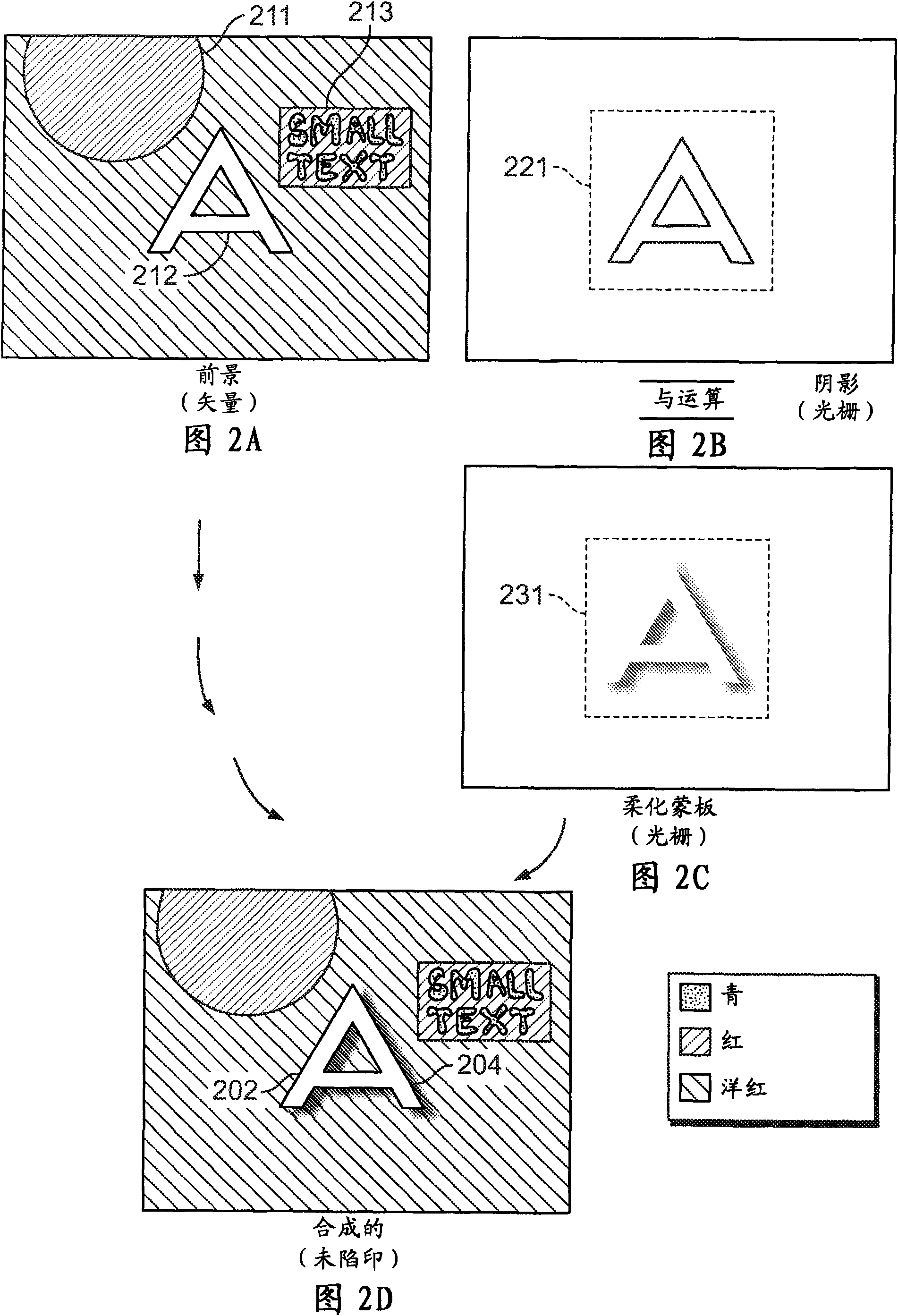
In some cases, such as for diagrams that include cast shadows, previous automatic trapping techniques produced undesired results

Method used


Image

  • Automatic trapping of drop shadows
  • Automatic trapping of drop shadows
  • Automatic trapping of drop shadows

Examples


Embodiment Construction

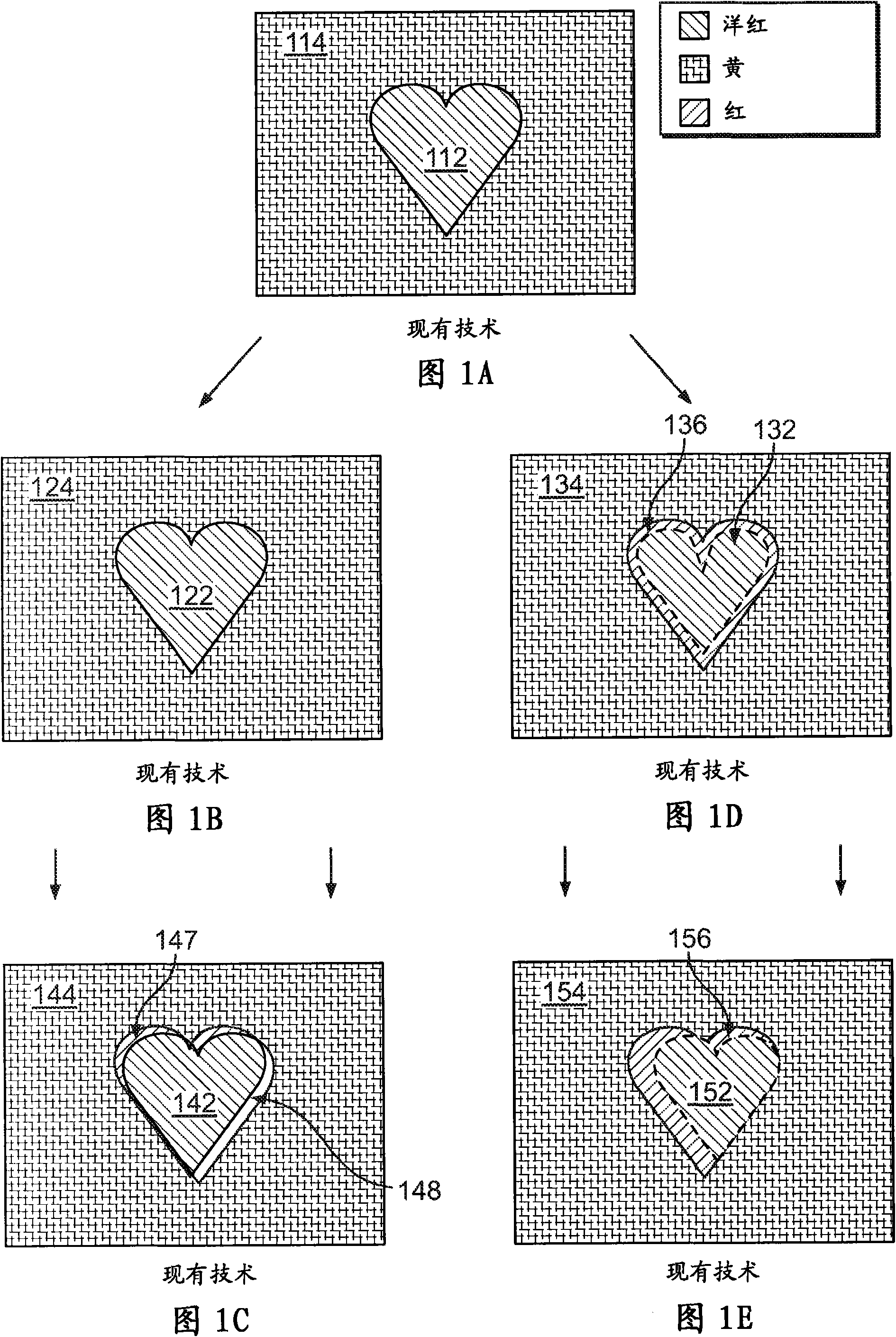
[0025] Figure 1A to Figure 1E A computer illustrated trapping is shown. Figure 1A An original rendering of the diagram including a magenta heart shape 112 over a yellow area 114 is shown. For example, the illustration may be printed on a four-color offset lithographic printing device having cyan, magenta, yellow, and black inks. The colors and printing techniques in this example are for illustration purposes. Trapping can be applied equally to other colors and ink types, as well as other printing techniques.

[0026] Figure 1B show Figure 1A An untrapped ideal print is plotted in . Heart 122 is printed in magenta ink, and area 124 is printed in yellow ink. The yellow and magenta inks are registered: they are perfectly adjacent, with no overlap and no gaps. Unfortunately, in the real world, colors are often misaligned. exist Figure 1C A defective print as illustrated as produced from misaligned printing units is shown in . exist Figure 1C The masked area 147 bet...


PUM


Abstract

Methods, program products and systems for automatically trapping drop shadows. For at least one segment incident to an atomic region which includes a drop shadow, and for each side of the segment, determining a first flattened color of the side's incident atomic region, and if the atomic region includes a drop shadow, additionally determining a second flattened color omitting the color of the drop shadow. An effective neutral density from the side's first flattened color is determined and, if the side has a second flattened color, the side's second flattened color. The two atomic regions incident to the segment are trapped based upon the effective neutral densities for the respective sides.

Description

technical field [0001] The present disclosure relates to automatically determining printing traps. Background technique [0002] Computer graphics illustrations are often composed of various types of primitives. Types of primitives include: rasterized graphics, glyphs, vector strokes, vector fills, image masks, soft masks, and gradients. Primitives typically include paths that define the boundaries of the primitive. Primitives can interact with each other (eg, through shading). Thus, unless otherwise indicated, any illustrations discussed are computer graphics illustrations. [0003] When printing an illustration, a printing device may use multiple printing units (eg, individual printing plates in a multi-plate printing apparatus) to print the colors in the illustration. If the printing unit is not properly aligned, it is characteristic that a colorless gap will appear between adjacent parts of the illustration having different colors. The gap may also grow if during th...

Claims


Application Information

Patent Timeline
Patent Type & Authority Applications(China)
IPC IPC(8): G06T15/50G09G5/00G09G5/02G06K9/40G06K9/36
CPCH04N1/58
Inventor S·R·亚汉恩R·史蒂文森D·R·贝克尔
Owner ADOBE INC
Learn More