
Image reading devices

An image reading device and image reading technology, which are applied in the directions of image communication, electrical components, etc., can solve problems such as damage to the function of the roller 101.

Active Publication Date: 2009-10-07
BROTHER KOGYO KK
View PDF1 Cites 13 Cited by
  • Summary
  • Abstract
  • Description
  • Claims
  • Application Information

AI Technical Summary

Problems solved by technology

Therefore, the upward urging force generated by the spring 102 acts on the base end D of the rotating shaft 104. On the contrary, at the abutting position A, a downward pressing force acts on the roller 101, so the roller 101 appears as shown by the dotted line. deformation, will damage the function of the roller 101

Method used


Image

  • Image reading devices
  • Image reading devices
  • Image reading devices

Examples


Embodiment Construction

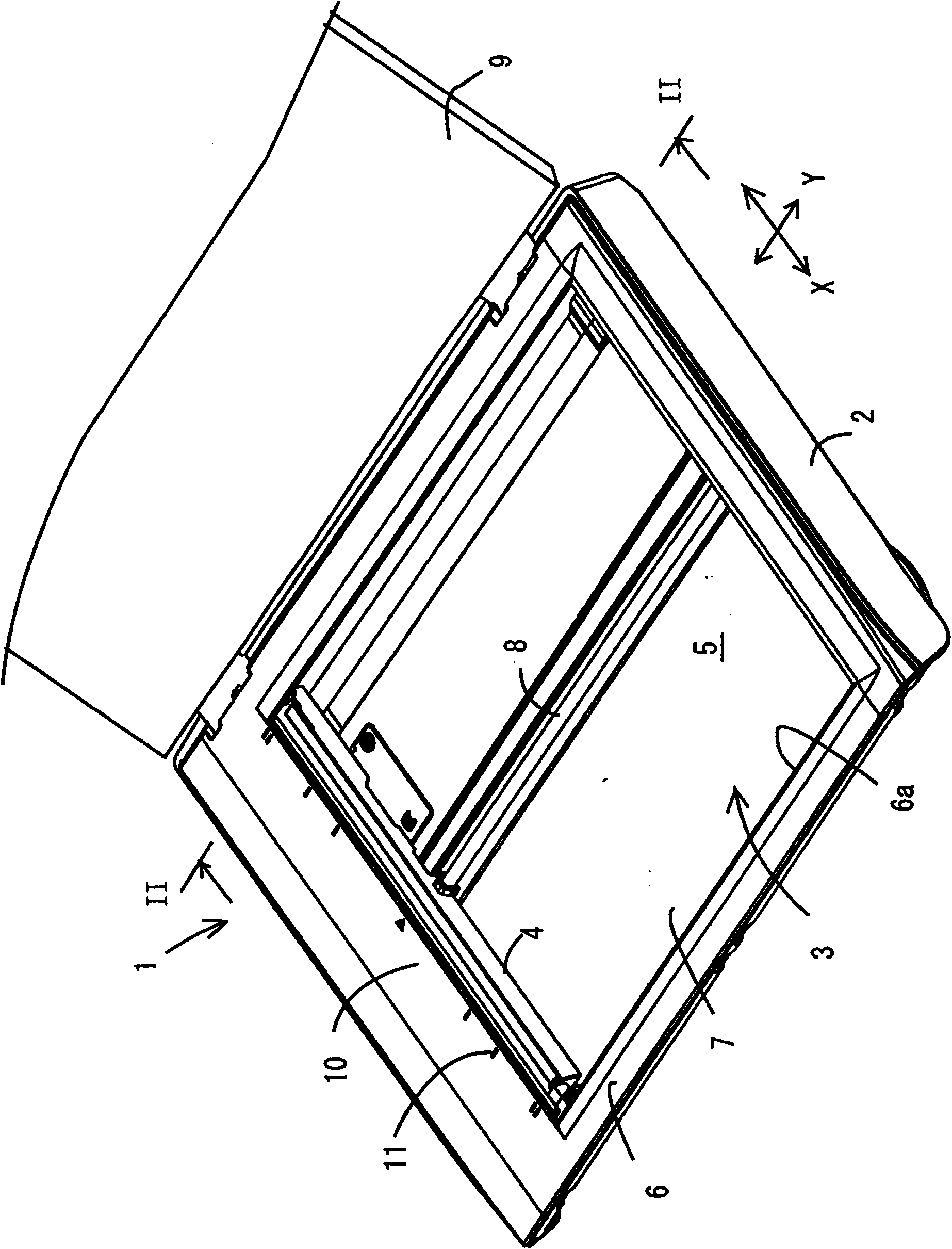
[0022] Embodiments of the present invention are described below. figure 1 It is a perspective view of an image reading device 1, which can be applied to a single scanning device, or can also be applied to a multifunctional image reading device having multiple functions such as a facsimile function, a copy function, a print function, and a scan function. take part.

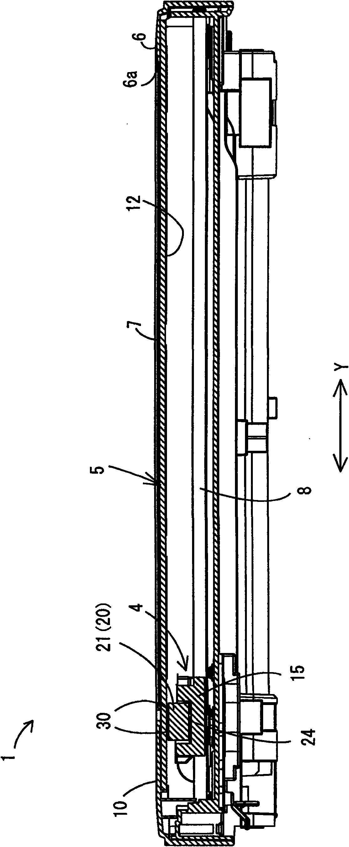
[0023] Such as figure 1 As shown in the image reading device 1 , a document table 3 on which a document is placed is provided on the upper side of the main body casing 2 , and a CIS image scanning device as the image reading unit 4 is movably disposed below it. On the top of the image reading device 1, a rear end ( figure 1 The upper right side) is the cover body 9 that can be opened and closed at the center, and the size can cover the original table 3 as a whole.

[0024] Although not shown, a plurality of keys such as a power switch of the image reading device 1 and a start key for instructing to read a docume...


PUM


Abstract

An image reading device comprises the following components: a document mounting plate; an image reading unit which has a length direction in a direction along the first edge of the mounting surface; and a moving unit which is configured oppositely with the mounting back surface at the opposite side of the mounting surface and moves the image reading unit in a direction of a second edge orthogonalwith the first edge. The image reading unit comprises the following components: a photoelectric converting part which is opposite with the placing back surface for reading the image on the document; aframe body which holds the photoelectric converting part and has length direction in a direction along the first edge; driven rotating bodies which are configured at two ends in the length directionof the frame body and rotates along with the moving of the image reading unit; a holding unit which supports the frame body and is connected with the moving unit for moving the frame body in a direction along the second edge; and a force applying unit which is configured between the holding unit and the frame body and faces the mounting back surface to exert force for keeping balance with the composite force of the pressing force from the mounting back surface to the driven rotating object when the driven rotating body abuts against the mounting back surface.

Description

technical field [0001] The present invention relates to a so-called flatbed image reading device that reads a document placed on a document placement plate. Background technique [0002] Conventionally, there has been known a so-called flatbed image reading device in which a document is placed on a document placing plate such as glass with the recording side facing down, and an image reading unit (image scanning device) arranged below the document placing plate ) to scan and read the image on the original. This type of image reading unit has a photoelectric conversion unit that converts reflected light from a document into an electrical signal for reading, and its types include CCD (Charge Coupled Devices: Charge Coupled Devices) and CIS (Contact Image Sensor: Contact Image Sensor) Wait. In particular, since the CIS is a contact-type reading method that reads close to the original, the distance between the CIS and the original greatly affects the reading accuracy. Therefo...

Claims


Application Information

Patent Timeline
Patent Type & Authority Applications(China)
IPC IPC(8): H04N1/04H04N1/10
CPCH04N2201/0456H04N1/1017H04N2201/02404H04N1/193
Inventor 刑部吉记
Owner BROTHER KOGYO KK
Learn More